Automate Deployments to Amazon EKS with Skaffold and GitHub Actions

Montag, 28 Februar, 2022

Creating a DevOps workflow to optimize application deployments to your Kubernetes cluster can be a complex journey. I recently demonstrated how to optimize your local K8s development workflow with Rancher Desktop and Skaffold. If you haven’t seen it yet, you can watch it by viewing the video below.

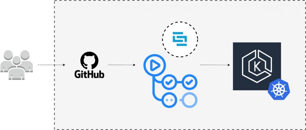
You might be wondering, “What happens next?” How do you extend this solution beyond a local setup to a real-world pipeline with a remote cluster? This tutorial responds to that question and will walk you through how to create a CI/CD pipeline for a Node.js application using Skaffold and GitHub Actions to an EKS cluster.

All the source code for this tutorial can be found in this repository.

Objectives

By the end of this tutorial, you’ll be able to:

1. Configure your application to work with Skaffold

2. Configure a CI stage for automated testing and building with GitHub Actions

3. Connect GitHub Actions CI with Amazon EKS cluster

4. Automate application testing, building, and deploying to an Amazon EKS cluster.

Prerequisites

To follow this tutorial, you’ll need the following:

-An AWS account.

-AWS CLI is installed on your local machine.

-AWS profile configured with the AWS CLI. You will also use this profile for the CI stage in GitHub Actions.

-A DockerHub account.

-Node.js version 10 or higher installed on your local machine.

-kubectl is installed on your local machine.

-Have a basic understanding of JavaScript.

-Have a basic understanding of IaC (Infrastructure as Code).

-Have a basic understanding of Kubernetes.

-A free GitHub account, with git installed on your local machine.

-An Amazon EKS cluster. You can clone this repository that contains a Terraform module to provision an EKS cluster in AWS. The repository README.md file contains a guide on how to use the module for cluster creation. Alternatively, you can use `eksctl` to create a cluster automatically. Running an Amazon EKS cluster will cost you $0.10 per hour. Remember to destroy your infrastructure once you are done with this tutorial to avoid additional operational charges.

Understanding CI/CD Process

Getting your CI/CD process right is a crucial step in your team’s DevOps lifecycle. The CI step is essentially automating the ongoing process of integrating the software from the different contributors in a project’s version control system, in this case, GitHub. The CI automatically tests the source code for quality checks and makes sure the application builds as expected.

The continuous deployment step picks up from there and automates the deployment of your application using the successful build from the CI stage.

Create Amazon EKS cluster

As mentioned above, you can clone or fork this repository that contains the relevant Terraform source code to automate the provisioning of an EKS cluster in your AWS account. To follow this approach, ensure that you have Terraform installed on your local machine. Alternatively, you can also use eksctl to provision your cluster. The AWS profile you use for this step will have full administrative access to the cluster by default. To communicate with the created cluster via kubectl, ensure your AWS CLI is configured with the same AWS profile.

You can view and confirm the AWS profile in use by running the following command:

aws sts get-caller-identity

Once your K8s cluster is up and running, you can verify the connection to the cluster by running `kubectl cluster-info` or `kubectl config current-context`.

Application Overview and Dockerfile

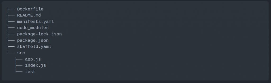
The next step is to create a directory on your local machine for the application source code. This directory should have the following folder structure (in the code block below). Ensure that the folder is a git repository by running the `git init` command.

Application Source Code

To create a package.json file from scratch, you can run the `npm init` command in the root directory and respond to the relevant questions you are prompted with. You can then proceed to install the following dependencies required for this project.

npm install body-parser cors express 
npm install -D chai mocha supertest nodemon

After that, add the following scripts to the generated package.json:

scripts: {
  start: "node src/index.js",
  dev: "nodemon src/index.js",
  test: "mocha 'src/test/**/*.js'"
},

Your final package.json file should look like the one below.

{
  "name": "nodejs-express-test",
  "version": "1.0.0",
  "description": "",
  "main": "index.js",
  "scripts": {
    "start": "node src/index.js",
    "dev": "nodemon src/index.js",
    "test": "mocha 'src/test/**/*.js'"
  },
  "repository": {
    "type": "git",
    "url": "git+<your-github-uri>"
  },
  "author": "<Your Name>",
  "license": "ISC",
  "dependencies": {
    "body-parser": "^1.19.0",
    "cors": "^2.8.5",
    "express": "^4.17.1"
  },
  "devDependencies": {
    "chai": "^4.3.4",
    "mocha": "^9.0.2",
    "nodemon": "^2.0.12",
    "supertest": "^6.1.3"
  }
}

Update the app.js file to initialize the Express web framework and add a single route for the application.

// Express App Setup
const express = require('express');
const http = require('http');
const bodyParser = require('body-parser');
const cors = require('cors');


// Initialization
const app = express();
app.use(cors());
app.use(bodyParser.json());


// Express route handlers
app.get('/test', (req, res) => {
  res.status(200).send({ text: 'Simple Node App Is Working As Expected!' });
});


module.exports = app;

Next, update the index.js in the root of the src directory with the following code to start the webserver and configure it to listen for traffic on port `8080`.

const http = require('http');
const app = require('./app');


// Server
const port = process.env.PORT || 8080;
const server = http.createServer(app);
server.listen(port, () => console.log(`Server running on port ${port}`));

The last step related to the application is the test folder which will contain the index.js file with code to test the single route you’ve added to our application.

You can redirect to the index.js file in the test folder and add code to test the route you added to the application.

const { expect } = require('chai');
const { agent } = require('supertest');
const app = require('../app');


const request = agent;


describe('Some controller', () => {
  it('Get request to /test returns some text', async () => {
    const res = await request(app).get('/test');
    const textResponse = res.body;
    expect(res.status).to.equal(200);
    expect(textResponse.text).to.be.a('string');
    expect(textResponse.text).to.equal('Simple Node App Is Working As Expected!');
  });
});

Application Dockerfile

Later on, we will configure Skaffold to use Docker to build our container image. You can proceed to create a Dockerfile with the following content:

FROM node:14-alpine
WORKDIR /usr/src/app
COPY ["package.json", "package-lock.json*", "npm-shrinkwrap.json*", "./"]
RUN npm install 
COPY . .
EXPOSE 8080
RUN chown -R node /usr/src/app
USER node
CMD ["npm", "start"]

Kubernetes Manifest Files for Application

The next step is to add the manifest files with the resources that Skaffold will deploy to your Kubernetes cluster. These files will be deployed continuously based on the integrated changes from the CI stage of the pipeline. You will be deploying a Deployment with three replicas and a LoadBalancer service to proxy traffic to the running Pods. These resources can be added to a single file called manifests.yaml.

apiVersion: apps/v1
kind: Deployment
metadata:
 name: express-test
spec:
 replicas: 3
 selector:
   matchLabels:
     app: express-test
 template:
   metadata:
     labels:
       app: express-test
   spec:
     containers:
     - name: express-test
       image: <your-docker-hub-account-id>/express-test
       resources:
          limits:
            memory: 128Mi
            cpu: 500m
       ports:
       - containerPort: 8080
---
apiVersion: v1
kind: Service
metadata:
  name: express-test-svc
spec:
  selector:
    app: express-test
  type: LoadBalancer
  ports:
  - protocol: TCP
    port: 8080
    targetPort: 8080

Skaffold Configuration File

In this section, you’ll populate your Skaffold configuration file (skaffold.yaml). This file will determine how your application is built and deployed by the Skaffold CLI tool in the CI stage of your pipeline. Your file will specify Docker as the image builder with the Dockerfile you created earlier to define the steps of how the image should be built. By default, Skaffold will use the gitCommit to tag the image create the Deployment manifest file with this image tag.

This configuration file will also contain a step for testing the application’s container image by executing the `npm run test` command that we added to the scripts section of the package.json file. Once the image has been successfully built and tested, it will be pushed to your Docker Hub account in the repository that you specify in the tag prefix.

Finally, we’ll specify that we want Skaffold to use kubectl to deploy the manifest file resources in the manifest.yaml file.

The complete configuration file will look like this:

apiVersion: skaffold/v2beta26
kind: Config
metadata:
  name: nodejs-express-test
build:
  artifacts:
  - image: <your-docker-hub-account-id>/express-test
    docker:
      dockerfile: Dockerfile
test:
  - context: .
    image: <your-docker-hub-account-id>/express-test
    custom:
      - command: npm run test
deploy:
  kubectl:
    manifests:
    - manifests.yaml

GitHub Secrets and GitHub Actions YAML File

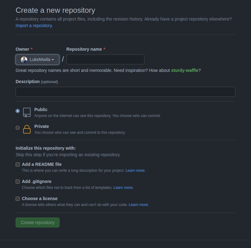
In this section, you will create a remote repository for your project in GitHub. In addition to this, you will add secrets for your CI environment and a configuration file for the GitHub Actions CI stage.

Proceed to create a repository in GitHub and complete the fields you will be presented with. This will be the remote repository for the local one you created in an earlier step.

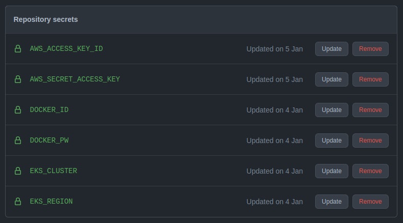
After you’ve created your repository, go to the repo Settings page. Under Security, select Secrets > Actions. In this section, you can create sensitive configuration data that will be exposed during the CI runtime as environment variables.

Proceed to create the following secrets:

-AWS_ACCCESS_KEY_ID – This is the AWS-generated Access Key for the profile you used to provision your cluster earlier.

-AWS_SECRET_ACCESS_KEY – This is the AWS-generated Secret Access Key for the profile you used to provision your cluster earlier.

-DOCKER_ID – This is the Docker ID for your DockerHub account.

-DOCKER_PW – This is the password for your DockerHub account.

-EKS_CLUSTER – This is the name you gave to your EKS cluster.

-EKS_REGION – This is the region where your EKS cluster has been provisioned.

Lastly, you are going to create a configuration file (main.yml) that will declare how the pipeline will be triggered, the branch to be used, and the steps that your CI/CD process should follow. As outlined at the start, this file will live in the .github/workflows folder and will be used by GitHub Actions.

The steps that we want to define are as follows:

-Expose our Repository Secrets as environment variables

-Install Node.js dependencies for the application

-Log in to Docker registry

-Install kubectl

-Install Skaffold

-Cache skaffold image builds & config

-Check that the AWS CLI is installed and configure your profile

-Connect to the EKS cluster

-Build and deploy to the EKS cluster with Skaffold

-Verify deployment

You can proceed to update the main.yml file with the following content.

name: 'Build & Deploy to EKS'
on:
  push:
    branches:
      - main
env:
  AWS_ACCESS_KEY_ID: ${{ secrets.AWS_ACCESS_KEY_ID }}
  AWS_SECRET_ACCESS_KEY: ${{ secrets.AWS_SECRET_ACCESS_KEY }}
  EKS_CLUSTER: ${{ secrets.EKS_CLUSTER }}
  EKS_REGION: ${{ secrets.EKS_REGION }}
  DOCKER_ID: ${{ secrets.DOCKER_ID }}
  DOCKER_PW: ${{ secrets.DOCKER_PW }}
jobs:
  deploy:
    name: Deploy
    runs-on: ubuntu-latest
    env:
      ACTIONS_ALLOW_UNSECURE_COMMANDS: 'true'
    steps:
      # Install Node.js dependencies
      - uses: actions/checkout@v2
      - uses: actions/setup-node@v2
        with:
          node-version: '14'
      - run: npm install
      - run: npm test
      # Login to Docker registry
      - name: Login to Docker Hub
        uses: docker/login-action@v1
        with:
          username: ${{ secrets.DOCKER_ID }}
          password: ${{ secrets.DOCKER_PW }}
      # Install kubectl
      - name: Install kubectl
        run: |
          curl -LO "https://dl.k8s.io/release/$(curl -L -s https://dl.k8s.io/release/stable.txt)/bin/linux/amd64/kubectl"
          curl -LO "https://dl.k8s.io/$(curl -L -s https://dl.k8s.io/release/stable.txt)/bin/linux/amd64/kubectl.sha256"
          echo "$(<kubectl.sha256) kubectl" | sha256sum --check


          sudo install -o root -g root -m 0755 kubectl /usr/local/bin/kubectl
          kubectl version --client
      # Install Skaffold
      - name: Install Skaffold
        run: |
          curl -Lo skaffold https://storage.googleapis.com/skaffold/releases/latest/skaffold-linux-amd64 && \
          sudo install skaffold /usr/local/bin/
          skaffold version
      # Cache skaffold image builds & config
      - name: Cache skaffold image builds & config
        uses: actions/cache@v2
        with:
          path: ~/.skaffold/
          key: fixed-${{ github.sha }}
      # Check AWS version and configure profile
      - name: Check AWS version
        run: |
          aws --version
          aws configure set aws_access_key_id $AWS_ACCESS_KEY_ID
          aws configure set aws_secret_access_key $AWS_SECRET_ACCESS_KEY
          aws configure set region $EKS_REGION
          aws sts get-caller-identity
      # Connect to EKS cluster
      - name: Connect to EKS cluster 
        run: aws eks --region $EKS_REGION update-kubeconfig --name $EKS_CLUSTER
      # Build and deploy to EKS cluster
      - name: Build and then deploy to EKS cluster with Skaffold
        run: skaffold run
      # Verify deployment
      - name: Verify the deployment
        run: kubectl get pods

Once you’ve updated this file, you can commit all the changes in your local repository and push them to the remote repository you created.

git add .
git commit -m "other: initial commit"
git remote add origin <your-remote-repository>
git push -u origin <main-branch-name>

Reviewing Pipeline Success

After pushing your changes, you can track the deployment in the Actions page of the remote repository you set up in your GitHub profile.
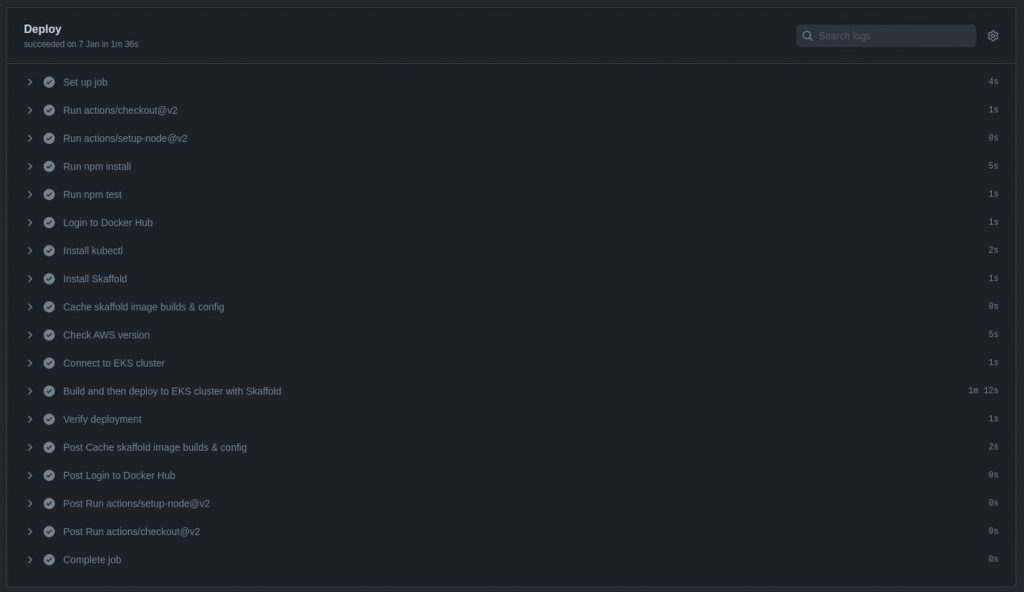
Conclusion

This tutorial taught you how to create automated deployments to an Amazon EKS cluster using Skaffold and GitHub Actions. As mentioned in the introduction, all the source code for this tutorial can be found in this repository. If you’re interested in a video walk-through of this post, you can watch the video below.

Make sure to destroy the following infrastructure provisioned in your AWS account:

-Load Balancer created by service resource in Kubernetes.

-Amazon EKS cluster

-VPC and all networking infrastructure created to support EKS cluster

Let’s continue the conversation! Join the SUSE & Rancher Community where you can further your Kubernetes knowledge and share your experience.

Run Your First Secure and DNS with Rancher

Montag, 29 November, 2021

In the previous article, we installed Rancher on the localhost and run the necessary CI/CD tools. This article will look at how to make our environment liveable on the Internet. We will use Route53 – domain registration and DNS-zones hosting, cert-manager – Let’s Encrypt wildcard certificates and external-dns – synchronizing Ingresses with DNS Route53.

A little personal experience

Why is Rancher good? Because those who do not want to understand the code of manifests and want to run what is required in manual mode can do this through an excellent graphical interface.

Register domain

I’m using Route53, but you can choose another supported provider for cert-manager and external-dns. The reason is that many applications work well with it and the integration is usually not difficult.

Register a new domain using the input field on the Dashboard screen. After completing the registration process in the Hosted zones section, you will see a new zone. Since we want to provide public access, we will use this zone for the production.

Create subdomain Hosted Zones

We will also have three zones: for dev.domain, stage.domain and release.domain as subdomains. Use the Create hosted zone button to create subdomains. For the subdomains to work, it is necessary to add records of NS-servers to the primary hosted zone, the way they are indicated in the subdomain zones. Create the same A-records in the main zone, this is domain and www.domain and dev.domain, stage.domain, release.domain in subdomains hosted zones. This is needed to issue certificates, since the provider checks for A-record before issuing a certificate.

The provider gives me a static IP-address and on the router, I made a forwarding to the bridge interface server IP address where we deployed everything in the previous article. It is this external address that needs to be specified in the A-records.

Create IAM for cert-manager and external-dns

In the IAM management console, create two policies with the following content:

Next, you need to create two users, assign them policies, and copy their credentials. In the documentation on cert-manager and external-dns, this is not an obvious point since they deal with cases with roles and this is misleading, but we will not use roles.

There are many articles on the Internet on how to do this in the cloud in various variations, but if you install on your local server everything is a little different.

Run cert-manager in Rancher-cluster

Add helm-char repo for cert-manager:

For cert-manager use default values.

prometheus:  
  enabled: false
installCRDs: true

Create ClusterIssuers for Hosted Zones

ClusterIssuer:

apiVersion: cert-manager.io/v1
kind: ClusterIssuer
metadata:
  name: letsencrypt-prod
spec:
  acme:
    email: certs@domain.io
    server: https://acme-v02.api.letsencrypt.org/directory
    privateKeySecretRef:
      name: domain-io-cluster-issuer-account-key
        solvers:
        - selector:
             dnsZones: 
                 - "domain.io"
      dns01:
        route53:
          region: eu-central-1
          accessKeyID: AKIAXXXXXXXXXXXXX
          secretAccessKeySecretRef:
            name: prod-route53-credentials-secret
            key: secret-access-key

And repeat this for dev.domain.io, stage.domain.io, release.domain.io, change ClusterIssuer name, and dnsZone, change privateKeySecretRef:

Request wildcard certificates for you Ingresses

We will use a wildcard certificate with validation through the provider’s DNS:

apiVersion: cert-manager.io/v1
kind: Certificate
metadata:
  name: domain-io
  namespace: domain
spec:
  secretName: domain-io-tls
  issuerRef:
    name: letsencrypt-prod
    kind: ClusterIssuer
  dnsNames:
  - '*.domain.io' 
  - domain.io

And repeat this for *.dev.domain.io, *.stage.domain.io, *.release.domain.io change namespace, secretName, ClusterIssuer Name.

Changes should occur in the section, certificates should appear, the normal status is Active and the color is green:

Run Ingresses for Your App

Since we issued wildcard certificates in advance and they will be updated independently, we can specify this secret for different domains in the settings. To synchronize secrets between namespaces, you can, for example, use a kubed.

Secure access for non-production zones

You can use client certificate validation to secure your development and test environments. To do this, you need to issue several self-signed certificates and add annotations to the ingress settings:

    nginx.ingress.kubernetes.io/auth-tls-pass-certificate-to-upstream: "true"
    nginx.ingress.kubernetes.io/auth-tls-secret: feature/ingresses-cert-dev <--feature - namespace
    nginx.ingress.kubernetes.io/auth-tls-verify-client: "on"
    nginx.ingress.kubernetes.io/auth-tls-verify-depth: "1"

More details can be found here.

For convert pem and key copy to different files, then give the command:

openssl pkcs12 -export -out developer.pfx -inkey developer.key -in developer.pem

and add pfx to chrome in settings.

Run external-dns

Add helm-chart repo:

Values:

aws:
  apiRetries: 3
  assumeRoleArn: ''
  batchChangeSize: 1000
  credentials:
    accessKey: AKIAXXXXXXXXXXXXX
    mountPath: /.aws
    secretKey: -->secret-from-iam<--
    secretName: ''
  evaluateTargetHealth: ''
  preferCNAME: ''
  region: eu-central-1
  zoneTags: []
  zoneType: ''
crd:
  apiversion: externaldns.k8s.io/v1alpha1
  create: true
  kind: DNSEndpoint
sources:
  - service
  - ingress
  - crd
txtOwnerId: sandbox
policy: sync

Create CRD: CRDmanifest

Create DNSendpoint

DNSendpoint:

apiVersion: externaldns.k8s.io/v1alpha1
kind: DNSEndpoint
metadata:
  name: examplednsrecord
  namespace: feature
spec:
  endpoints:
  - dnsName: test1.dev.domain.io
    recordTTL: 180
    recordType: A
    targets:
    - <YOU-EXTERNAL-IP-ADDRESS>

In log:

time="2021-11-25T23:19:37Z" level=info msg="All records are already up to date"
time="2021-11-25T23:20:38Z" level=info msg="Applying provider record filter for domains: [domain.io. .domain.io. release.domain.io. .release.domain.io. stage.domain.io. .stage.domain.io. dev.domain.io. .dev.domain.io.]"

Create:

time="2021-11-25T23:54:57Z" level=info msg="Desired change: CREATE test1.dev.domain.io A [Id: /hostedzone/ZXXXXXXXXXXXDN]"
time="2021-11-25T23:54:57Z" level=info msg="Desired change: CREATE test1.dev.domain.io TXT [Id: /hostedzone/ZXXXXXXXXXXXXXXXXDN]"
time="2021-11-25T23:54:57Z" level=info msg="2 record(s) in zone dev.domain.io. [Id: /hostedzone/ZXXXXXXXXXXXXXXXDN] were successfully updated"

Delete:

time="2021-11-25T23:59:59Z" level=info msg="Desired change: DELETE test1.dev.domain.io A [Id: /hostedzone/ZXXXXXXXXXXXXXDN]"
time="2021-11-25T23:59:59Z" level=info msg="Desired change: DELETE test1.dev.domain.io TXT [Id: /hostedzone/ZXXXXXXXXXXXXXDN]"
time="2021-11-25T23:59:59Z" level=info msg="2 record(s) in zone dev.domain.io. [Id: /hostedzone/ZXXXXXXXXXXXXXXXXXXDN] were successfully updated"

Conclusion

As it turns out for your own development, it is quite easy to raise the full stack on a single server and even post it on the Internet.

Test zones:

https://www.pregap.io

https://dev.pregap.io – secure access

https://stage.pregap.io – secure access

https://release.pregap.io – secure access

Is Cloud Native Development Worth It?    

Donnerstag, 18 November, 2021
The ‚digital transformation‘ revolution across industries enables businesses to develop and deploy applications faster and simplify the management of such applications in a cloud environment. These applications are designed to embrace new technological changes with flexibility.

The idea behind cloud native app development is to design applications that leverage the power of the cloud, take advantage of its ability to scale, and quickly recover in the event of infrastructure failure. Developers and architects are increasingly using a set of tools and design principles to support the development of modern applications that run on public, private, and hybrid cloud environments.

Cloud native applications are developed based on microservices architecture. At the core of the application’s architecture, small software modules, often known as microservices, are designed to execute different functions independently. This enables developers to make changes to a single microservice without affecting the entire application. Ultimately, this leads to a more flexible and faster application delivery adaptable to the cloud architecture.

Frequent changes and updates made to the infrastructure are possible thanks to containerization, virtualization, and several other aspects constituting the entire application development being cloud native. But the real question is, is cloud native application development worth it? Are there actual benefits achieved when enterprises adopt cloud native development strategies over the legacy technology infrastructure approach? In this article, we’ll dive deeper to compare the two.

Should  You Adopt a Cloud Native over Legacy Application Development Approach?

Cloud computing is becoming more popular among enterprises offering their technology solutions online. More tech-savvy enterprises are deploying game-changing technology solutions, and cloud native applications are helping them stay ahead of the competition. Here are some of the major feature comparisons of the two.

Speed

While customers operate in a fast-paced, innovative environment, frequent changes and improvements to the infrastructure are necessary to keep up with their expectations. To keep up with these developments, enterprises must have the proper structure and policies to conveniently improve or bring new products to market without compromising security and quality.

Applications built to embrace cloud native technology enjoy the speed at which their improvements are implemented in the production environment, thanks to the following features.

Microservices

Cloud native applications are built on microservices architecture. The application is broken down into a series of independent modules or services ,with each service consuming appropriate technology stack and data. Communication between modules is often done over APIs and message brokers.

Microservices frequently improve the code to add new features and functionality without interfering with the entire application infrastructure. Microservices‘ isolated nature makes it easier for new developers in the team to comprehend the code base and make contributions faster. This approach facilitates speed and flexibility at which improvements are being made to the infrastructure. In comparison,  an infrastructure consuming the monolithic architecture would slowly see new features and enhancements being pushed to production. Monolithic applications are complex and tightly coupled, meaning slight code changes must be harmonized to avoid failures. As a result, this slows down the deployment process.

CI/CD Automation Concepts

The speed at which applications are developed, deployed, and managed has primarily been attributed to adopting Continuous Integration and Continuous Development (CI/CD).

Improvement strategies include new code changes to the infrastructure through an automated checklist in a CI/CD pipeline and testing that application standards are met before being pushed to a production environment.

When implemented on cloud native applications architecture, CI/CD streamlines the entire development and deployment phases, shortening the time in which the new features are delivered to production.

Implementing CI/CD highly improves productivity in organizations to everyone’s benefit. Automated CI/CD pipelines make deployments predictable, freeing developers from repetitive tasks to focus on higher-value tasks.

On-demand infrastructure Scaling

Enterprises should opt for cloud native architecture over traditional application development approaches to easily provision computing resources to their infrastructure on demand.

Rather than having IT support applications based on estimates of what infrastructure resources are needed, the cloud native approach promotes automated provisioning of computing resources on demand.

This approach helps applications run smoothly by continuously monitoring the health of your infrastructure for workloads that would otherwise fail.

The cloud native development approach is based on orchestration technology that provides developers insights and control to scale the infrastructure to the organization’s liking. Let’s look at how the following features help achieve infrastructure scaling.

Containerization

Cloud native applications are built based on container technology where microservices, operating system libraries, and dependencies are bundled together to create single lightweight executables called container images.

These container images are stored in an online registry catalog for easy access by the runtime environment and developers making updates on them.

Microservices deployed as containers should be able to scale in and out, depending on the load spikes.

Containerization promotes portability by ensuring the executable packaging is uniform and runs consistently across the developer’s local and deployment environments.

Orchestration

Let’s talk orchestration in cloud native application development. Orchestration automates deploying, managing, and scaling microservice-based applications in containers.

Container orchestration tools communicate with user-created schedules (YAML, JSON files) to describe the desired state of your application. Once your application is deployed, the orchestration tool uses the defined specifications to manage the container throughout its lifecycle.

Auto-Scaling

Automating cloud native workflows ensures that the infrastructure automatically self-provisions itself when in need of resources. Health checks and auto-healing features are implemented in the infrastructure when under development to ensure that the infrastructure runs smoothly without manual intervention.

You are less likely to encounter service downtime because of this. Your infrastructure is automatically set to auto-detect an increase in workloads that would otherwise result in failure and automatically scales to a working machine.

Optimized Cost of Operation

Developing cloud native applications eliminates the need for hardware data centers that would otherwise sit idle at any given point. The cloud native architecture enables a pay-per-use service model where organizations only pay for the services they need to support their infrastructure.

Opting for a cloud native approach over a traditional legacy system optimizes the cost incurred that would otherwise go toward maintenance. These costs appear in areas such as scheduled security improvements, database maintenance, and managing frequent downtimes. This usually becomes a burden for the IT department and can be partially solved by migrating to the cloud.

Applications developed to leverage the cloud result in optimized costs allocated to infrastructure management while maximizing efficiency.

Ease of Management

Cloud native service providers have built-in features to manage and monitor your infrastructure effortlessly. A good example, in this case, is serverless platforms like AWS Lambda and  Azure Functions. These platforms help developers manage their workflows by providing an execution environment and managing the infrastructure’s dependencies.

This gets rid of uncertainty in dependencies version and configuration settings required to run the infrastructure. Developing applications that run on legacy systems requires developers to update and maintain the dependencies manually. Eventually, this becomes a complicated practice with no consistency. Instead, the cloud native approach makes collaborating easier without having the “This application works on my system but fails on another machine ” discussion.

Also, since the application is divided into smaller, manageable microservices, developers can easily focus on specific units without worrying about interactions between them.

Challenges

Unfortunately, there are challenges to ramping up users to adopt the new technology, especially for enterprises with long-standing legacy applications. This is often a result of infrastructure differences and complexities faced when trying to implement cloud solutions.

A perfect example to visualize this challenge would be assigning admin roles in Azure VMware solutions. The CloudAdmin role would typically create and manage workloads in your cloud, while in an Azure VMware Solution, the cloud admin role has privileges that conflict with the VMware cloud solutions and on-premises.

It is important to note that in the Azure VMware solution, the cloud admin does not have access to the administrator user account. This revokes the permission roles to add identity sources like on-premises servers to vCenter, making infrastructure role management complex.

Conclusion

Legacy vs. Cloud Native Application Development: What’s Best?

While legacy application development has always been the standard baseline structure of how applications are developed and maintained, the surge in computing demands pushed for the disruption of platforms to handle this better.

More enterprises are now adopting the cloud native structure that focuses on infrastructure improvement to maximize its full potential. Cloud native at scale is a growing trend that strives to reshape the core structure of how applications should be developed.

Cloud native application development should be adopted over the legacy structure to embrace growing technology trends.

Are you struggling with building applications for the cloud?  Watch our 4-week On Demand Academy class, Accelerate Dev Workloads. You’ll learn how to develop cloud native applications easier and faster.

Introduction to Cloud Native Application Architecture    

Mittwoch, 17 November, 2021
Today, it is crucial that an organization’s application’s scalability matches its growth tempo. If you want your client’s app to be robust and easy to scale, you have to make the right architectural decisions.

Cloud native applications are proven more efficient than their traditional counterparts and much easier to scale due to containerization and running in the cloud.

In this blog, we’ll talk about what cloud native applications are and what benefits this architecture brings to real projects.

What is Cloud Native Application Architecture?

Cloud native is an approach to building and running apps that use the cloud. In layman’s terms, companies that use cloud native architecture are more likely to create new ideas, understand market trends and respond faster to their customers’ requests.

Cloud native applications are tied to the underlying infrastructure needed to support them. Today, this means deploying microservices through containers to dynamically provision resources according to user needs.

Each microservice can independently receive and transmit data through the service-level APIs. Although not required for an application to be considered „cloud native“ due to modularity, portability, and granular resource management, microservices are a natural fit for running applications in the cloud.

Scheme of Cloud Native Application

Cloud native application architecture consists of frontend and backend. 

  • The client-side or frontend is the application interface available for the end-user. It has protocols and ports configured for user-database access and interaction. An example of this is a web browser. 
  • The server-side or backend refers to the cloud itself. It consists of resources providing cloud computing services. It includes everything you need, like data storage, security, and virtual machines.

All applications hosted on the backend cloud server are protected due to built-in engine security, traffic management, and protocols. These protocols are intermediaries, or middleware, for establishing successful communication with each other.

What Are the Core Design Principles of Cloud Native Architecture?

To create and use cloud native applications, organizations need to rethink the approach to the development system and implement the fundamental principles of cloud native.

DevOps

DevOps is a cultural framework and environment in which software is created, tested, and released faster, more frequently, and consistently. DevOps practices allow developers to shorten software development cycles without compromising on quality.

CI/CD

Continuous integration (CI) is the automation of code change integration when numerous contributions are made to the same project. CI is considered one of the main best practices of DevOps culture because it allows developers to merge code more frequently into the central repository, where they are subject to builds and tests.

Continuous delivery (CD) is the process of constantly releasing updates, often through automated delivery. Continuous delivery makes the software release process reliable, and organizations can quickly deliver individual updates, features, or entire products.

Microservices

Microservices are an architectural approach to developing an application as a collection of small services; each service implements a business opportunity, starts its process, and communicates through its own API.

Each microservice can be deployed, upgraded, scaled, and restarted independently of other services in the same application, usually as part of an automated system, allowing frequent updates to live applications without impacting customers.

Containerization

Containerization is a software virtualization technique conducted at the operating system level and ensures the minimum use of resources required for the application’s launch.

Using virtualization at the operating system level, a single OS instance is dynamically partitioned into one or more isolated containers, each with a unique writeable file system and resource quota.

The low overhead of creating and deleting containers and the high packing density in a single VM make containers an ideal computational tool for deploying individual microservices.

Benefits of Cloud Native Architecture

Cloud native applications are built and deployed quickly by small teams of experts on platforms that provide easy scalability and hardware decoupling. This approach provides organizations greater flexibility, resiliency, and portability in cloud environments.

Strong Competitive Advantage

Cloud-based development is a transition to a new competitive environment with many convenient tools, no capital investment, and the ability to manage resources in minutes. Companies that can quickly create and deliver software to meet customer needs are more successful in the software age.

Increased Resilience

Cloud native development allows you to focus on resilience tools. The rapidly evolving cloud landscape helps developers and architects design systems that remain interactive regardless of environment freezes.

Improved Flexibility

Cloud systems allow you to quickly and efficiently manage the resources required to develop applications. Implementing a hybrid or multi-cloud environment will enable developers to use different infrastructures to meet business needs.

Streamlined Automation and Transformation

The automation of IT management inside the enterprise is a springboard for the effective transformation of other departments and teams.

In addition, it eliminates the risk of disruption due to human error as employees focus on controlling routine tasks rather than performing them directly.

Automated real-time patches and updates across all stack levels eliminate downtime and the need for operational experts with “manual management” expertise.

Comparison: Cloud Native Architecture vs. Legacy Architecture

The capabilities of the cloud allow both traditional monolithic applications and data operations to be transferred to it. However, many enterprises prefer to invest in a cloud native architecture from the start. Here is why:

Separation of Computation and Data Storage Improves Scalability

Datacenter servers are usually connected to direct-attached storage (DAS), which an enterprise can use to store temporary files, images, documents, or other purposes.

Relying on this model is dangerous because its processing power needs can rise and fall in very different ways than storage needs. The cloud enables object storage such as AWS S3 or ADLS, which can be purchased, optimized, and managed separately from computing requirements.

This way, you can easily add thousands of new users or expand the app’s functionality.

Cloud Object Storage Gives Better Adaptability

Cloud providers are under competitive pressure to improve and innovate in their storage services. Application architects who monitor closely and quickly adapt to these innovations will have an edge over competitors who have taken a wait-and-see attitude.

Alongside proprietary solutions, there are also many open source, cloud computing software projects like Rancher.

This container management platform provides users with a complete software stack that facilitates Kubernetes cluster management in a private or public cloud.

Cloud Native Architecture is More Reliable

The obvious advantage for those companies that have adopted a native cloud approach is the focus on agility, automation, and simplification.

For complex IT or business functions, their survival depends on the level of elaboration of their services. On the other hand, you need error protection to improve user productivity through increased levels of automation, built-in predictive intelligence, or machine learning to help keep your environment running optimally.

Cloud Native Architecture Makes Inter-Cloud Migration Easy

Every cloud provider has its cloud services (e.g., data warehousing, ETL, messaging) and provides a rich set of ready-made open source tools such as Spark, Kafka, MySQL, and many others.

While it sounds bold to say that using open source solutions makes it easy to move from one cloud to another, if cloud providers offer migration options, you won’t have to rewrite a significant part of the existing functionality.

Moreover, many IT architects see the future in the multi-cloud model, as many companies already deal with two or more cloud providers.

If your organization can skillfully use cloud services from different vendors, then the ability to determine the advantage of one cloud over another is good groundwork for the future justification of your decision.

Conclusion

Cloud native application architecture provides many benefits. This approach automates and integrates the concepts of continuous delivery, microservices, and containers for enhanced quality and streamlined delivery.

Applications that are built as cloud native can offer virtually unlimited computing power on demand. That’s why more and more developers today are choosing to build and run their applications as cloud native.

Want to make sure you don’t miss any of the action? Join the SUSE & Rancher Community to get updates on new content coming your way!

Terraform Resources to Provision a HA Kubernetes Cluster in the Cloud

Freitag, 22 Oktober, 2021

In the most recent classes of the Up & Running: Rancher course, I demonstrated how to provision both a single node and a highly available (HA) Kubernetes cluster on your local machine. However, it’s equally important to understand how to carry this out in a cloud environment if your Rancher server will be managing K8s clusters in the cloud.

In practice, an optimal approach would be to make use of Infrastructure as Code (IaC). If you’re completely new to IaC, you can read through an excellent resource by Nwani Victory who elaborates on the benefits of IaC in his article.

In this short post, I want to share some resources that make use of Terraform to automatically provision the necessary infrastructure to run Kubernetes in the cloud. Once your cluster is up and running, you can proceed to install Rancher using helm.

Provision Hosted Clusters (EKS, GKE, AKS)

Hosted clusters are a popular solution for running Kubernetes in a production environment. They offer users the chance to focus on the worker plane while the respective cloud provider assumes ownership, security, and optimization of the control plane and the data plane of your K8s cluster.

This GitHub project contains the relevant source code and a README.md file that outlines a step-by-step approach to provision hosted Kubernetes clusters in AWS, GCP, or Azure with Terraform. One cluster can then be used as the Rancher server to manage the other downstream clusters.

Link: https://github.com/SUSE-Rancher-Community/provision-hosted-clusters-eks-gke-aks-with-terraform

In a previous Kubernetes Master Class session, I dealt with how to manage hosted clusters with Rancher. If you missed it, you can watch the replay below.

Bootstrap RKE Kubernetes Cluster in AWS Environment

If you want to have full ownership of the different planes in the K8s architecture, you can use a CNCF-certified Kubernetes distribution like RKE.

This GitHub project contains the source code and steps to bootstrap a HA RKE cluster in AWS with a private cluster endpoint.

Link: https://github.com/LukeMwila/bootstrap-rke-cluster-in-aws

The repository has a README.md file explaining the steps for installation and usage. If you need additional context on how to make use of it, you can also watch the video below as I walk through the usage of the project.


If you use any of the above material for testing purposes, remember to destroy the resources you create through Terraform to avoid incurring additional costs.

What next?

You can watch the replay in the course material section if you missed the most recent session. You can find the recording here:

https://community.suse.com/posts/up-and-running-rancher-october-2021-installing-rancher-initial-setup-part-2

Be sure to join the next class where we’ll be looking at cluster operations with Rancher!

Managing Rancher Resources Using Pulumi as an Infrastructure as Code Tool

Dienstag, 19 Oktober, 2021

Using an Infrastructure as Code (IaC) solution to automate the management of your cloud resources is one of the recommended ways to reduce the toil that results from repetitive operations to manage your infrastructure.

In this article, you will learn about Infrastructure as Code and how to reduce toil by using IaC to provision your Rancher resources.

Prerequisites

This article contains a demo where Rancher resources were provisioned using Pulumi. You will need the following tools installed on your computer to follow along with the demo:

Introduction To Infrastructure As Code

Infrastructure as code (IaC) refers to managing resources within an infrastructure through a reusable definition file. Resources managed can include virtual machines, networks and storage units.

With IaC, your cloud resources are defined within a configuration file, and you can use an IaC tool to create the defined resources on your behalf.

IaC tools are split into two categories: Native IaC tools for tools built and used with public cloud providers such as ARM Template on Azure, and multi-cloud IaC tools that provision resources across different infrastructure providers (such as Terraform and Pulumi) for creating resources on Google CloudAWS and other platforms.

This article focuses on learning how to provision resources on a Rancher server using Pulumi.

Introducing Pulumi

Pulumi is an open source project that provides an SDK for you to manage cloud resources using one of the four supported programming languages. Similar to Terraform, Pulumi provides the free Pulumi cloud service by default to better manage the state of your provisioned resources across a team.

Note: The Windows Containers With Rancher and Terraform post on the rancher blog explains how to provision an RKE cluster using Terraform.

Used Pulumi Concepts

Before you move further, it would be helpful to have a simplified understanding of the following Pulumi concepts that are frequently used within this article.

Note: The Concepts & Architecture section within the Pulumi documentation contains all explanations of Pulumi’s concepts.

  • Stack: A stack within Pulumi is an independent instance containing your project. You can also liken a Pulumi stack to environments. Similar to the way you have development and production environments for your projects, you can also have multiple stacks containing various phases of your Pulumi project. This tutorial will use the default stack created when you bootstrap a new Pulumi project.

  • Inputs: Inputs are the arguments passed into a resource before creation. These arguments can be of various data values such as strings, arrays, or even numbers.

  • Outputs: Pulumi outputs are special values obtained from resources after they have been created. An example output could be the ID of the K3 cluster after it was created.

Creating Configuration Variables

Rancher API Keys

Your Rancher Management server will use an API token to authenticate the API requests made by Pulumi to create Rancher resources. API tokens are managed in the account page within the Rancher Management Console.

To create an API token, open your Rancher Management Console and click the profile avatar to reveal a dropdown. Click the Account & API Keys item from the dropdown to navigate to the account page.

From the account page, click the Create API Key button to create a new API Key.


Provide a preferred description for the API Key within the description text input on the next page. You can also set an expiry date for the API key by clicking the radio button for a preferred expiry period. Since the API key will create new resources, leave the scope dropdown at its default No Scope selection.

Click the Create button to save and exit the current page.

An Access Key, Secret Key, and Bearer Token will be displayed on the next page. Ensure you note the Bearer Token within a secure notepad as you will reference it when working with Pulumi.

Azure Service Principal Variables

Execute the Azure Active Directory ( ad ) command below to create a service principal to be used with Rancher:

az ad sp create-for-rbac -n "rancherK3Pulumi" --sdk-auth

As shown in the image below, the az command above returns a JSON response containing Client ID, Subscription ID, and Client Secret fields. Note the value of these fields in a secure location, as you will use them in the next step when storing credentials with Pulumi.

Setting Configuration Secrets

With the configuration variables created from the last section, let’s store them using Pulumi Secrets. The secret feature of Pulumi enables you to encrypt sensitive values used within your stack without the value into the stack’s state file.

Note: Replace the placeholders with the corresponding values obtained from the previous section.

Execute the series of commands below to store the environment variables used by Pulumi to provision Rancher resources.

The „–secret flag“ passed to some of the commands below will ensure the values are hashed before being stored in the pulumi.dev.yaml file.

# Rancher API Keys
pulumi config set rancher2:apiUrl <RANCEHR_API_URL>
pulumi config set rancher2:accessToken <RANCHER_ACCESS_TOKEN> --secret
pulumi config set PROJECT_ID <PROJECT_ID_TEXT>

# Azure Service Principal Credentials
pulumi config set SUBSCRIPTION_ID <SUBSCRIPTION_ID_TEXT>
pulumi config set --secret CLIENT_ID <CLIENT_ID_TEXT>
pulumi config set --secret CLIENT_SECRET <CLIENT_SECRET_TEXT>

Creating A Pulumi Project

Now that you understand what Pulumi is, we will use Pulumi to provision a Rancher Kubernetes cluster on a Rancher management server.

At a bird’s eye view, the image below shows a graph of all Rancher resources that will be provisioned within a Pulumi stack in this article.

Within the steps listed out below, you will gradually put together the resources for an RKE cluster.

  1. Execute the two commands below from your local terminal to create an empty directory (rancher-pulumi) and change your working directory into the new directory.

# create new directory
mkdir rancher-pulumi-js

# move into new directory
cd rancher-pulumi-js
  1. Execute the Pulumi command below to initialize a new Pulumi project using the javascript template within the empty directory.

The -n (name) flag passed to the command below will specify the Pulumi project name as rancher-pulumi-js.

pulumi new -n rancher-pulumi-js javascript

Using the JavaScript template specified in the command above, the Pulumi CLI will generate the boilerplate files needed to build a stack using the Node.js library for Pulumi.

Execute the NPM command below to install the @pulumi/rancher2 Rancher resource provider.

npm install @pulumi/rancher2 dotenv

Provisioning Rancher Resources

The code definition for the resources to be created will be stored in the generated index.js file. The steps below will guide you on creating a new Rancher namespace and provisioning an EKS cluster on AWS using Rancher.

  1. Add the code block’s content below into the index.js file to create a namespace within your Rancher project. You can liken a namespace to an isolated environment that contains resources within your project.

The code block contains a RANCHER_PREFIX variable that contains an identifier text. In the preceding code blocks, you will prefix this variable to the name of other resources created to indicate that they were created using Pulumi.

The Pulumi Config variable within the code block stores an instance of the Pulumi Config class. The required method is later executed to retrieve the configuration variables that were stored as secrets.

"use strict";
const pulumi = require("@pulumi/pulumi");
const rancher2 = require("@pulumi/rancher2");

const RANCHER_PREFIX = "rancher-pulumi"
const pulumiConfig = new pulumi.Config();

// Create a new rancher2 Namespace
new rancher2.Namespace(`${RANCHER_PREFIX}-namespace`, {
   containerResourceLimit: {
       limitsCpu: "20m",
       limitsMemory: "20Mi",
       requestsCpu: "1m",
       requestsMemory: "1Mi",
   },
   description: `Namespace to store resources created within ${RANCHER_PREFIX} project`,
   projectId: pulumiConfig.require('PROJECT_ID'),
   resourceQuota: {
       limit: {
           limitsCpu: "100m",
           limitsMemory: "100Mi",
           requestsStorage: "1Gi",
       }
   }
});

Similar to the Terraform Plan command, you can also use the Pulumi preview command to view the changes to your stack before they are applied.

The image below shows the diff log of the changes caused by adding the Rancher namespace resource.

  1. Next, add the cluster resource within the code block below into the index.js file to provision an RKE cluster within the new namespace.

const rkeCluster = new rancher2.Cluster(`${RANCHER_PREFIX}-rke-cluster`, {
   description: `RKE cluster created within ${RANCHER_PREFIX} project`,
   rkeConfig: {
       network: {
           plugin: "canal",
       },
   },

   clusterMonitoringInput: {
       answers: {
           "exporter-kubelets.https": true,
           "exporter-node.enabled": true,
           "exporter-node.ports.metrics.port": 9796,
           "exporter-node.resources.limits.cpu": "200m",
           "exporter-node.resources.limits.memory": "200Mi",
           "prometheus.persistence.enabled": "false",
           "prometheus.persistence.size": "50Gi",
           "prometheus.persistence.storageClass": "default",
           "prometheus.persistent.useReleaseName": "true",
           "prometheus.resources.core.limits.cpu": "1000m",
           "prometheus.resources.core.limits.memory": "1500Mi",
           "prometheus.resources.core.requests.cpu": "750m",
           "prometheus.resources.core.requests.memory": "750Mi",
           "prometheus.retention": "12h"
       },
       version: "0.1.0",
   }
})

The next step will be registering a node for the created cluster before it can be fully provisioned.

  1. Next, add the CloudCredential resource within the code block below to create a cloud credential containing your Azure Service Principal configuration. Cloud Credentials is a feature of Rancher that helps you securely store the credentials of an infrastructure needed to provision a cluster.

Without automation, you would need to use the Rancher Management dashboard to create a cloud credential. Visit the Rancher Documentation on Cloud Credentials to learn how to manage the credentials from your Rancher Management dashboard.

// Create a new rancher2 Cloud Credential
const rancherCloudCredential = new rancher2.CloudCredential("rancherCloudCredential", {
   description: `Cloud credential for ${RANCHER_PREFIX} project.`,
   azureCredentialConfig: {
       subscriptionId: pulumiConfig.require('SUBSCRIPTION_ID'),
       clientId: pulumiConfig.require('CLIENT_ID'),
       clientSecret: pulumiConfig.require('CLIENT_SECRET')
   }
});
  1. Add the NodeTemplate resource within the code block below into the index.js file to create a reusable NodeTemplate that uses Azure as an infrastructure provider. The Node Template resource will define the settings for the operating system running the nodes for the RKE cluster as a reusable template.

The Pulumi Rancher2 provider will specify most of the default settings for the NodeTemplate; however, the fields within the code block customize the NodeTemplate created.

// create a rancher node template
const rancherNodeTemplate = new rancher2.NodeTemplate("rancherNodeTemplate", {
   description: `NodeTemplate created by ${RANCHER_PREFIX} project using Azure`,
   cloudCredentialId: rancherCloudCredential.id,
   azureConfig: {
     storageType: "Standard_RAGRS",
       size: "Standard_B2s"
   }
});
  1. Add the NodePool resource into the index.js file to create a node pool for the RKE cluster created in step two.

// Create a new rancher2 Node Pool
const rancherNodePool = new rancher2.NodePool(`${RANCHER_PREFIX}-cluster-pool`, {
   clusterId: rkeCluster.id,
   hostnamePrefix: `${RANCHER_PREFIX}-cluster-0`,
   nodeTemplateId: rancherNodeTemplate.id,
   quantity: 1,
   controlPlane: true,
   etcd: true,
   worker: true,
});

At this point, you have added all the Pulumi objects to build a Rancher Kubernetes Engine cluster using Azure as an infrastructure provider. Now we can proceed to build the resources that have been defined in the index.js file.

Execute the Pulumi up command to generate an interactive plan of the changes within the stack. Select the yes option to apply the changes and create the Rancher Kubernetes Cluster.

The RKE cluster will take some minutes before it is fully provisioned and active. In the meantime, you can view the underlying resources created by viewing them through your Rancher management dashboard and the Azure portal.

Summary

Pulumi is a great tool that brings Infrastructure as Code a step closer to you by enabling the provisioning of resources using your preferred programming languages.

Within this blog post, we used the Rancher2 provider for Pulumi to provision a Kubernetes cluster using the Rancher Kubernetes Engine on Azure. The Rancher2 Provider API documentation for Pulumi provides details of other provider APIs you can use to create Rancher resources.

Overall, IaC helps you to build consistent cloud infrastructures across multiple environments. As long as the providers used by the IaC tools remain the same, you can always provision new resources executing a command.

Tags: ,, Category: Rancher Kubernetes Comments closed

Using MinIO as Backup Target for Rancher Longhorn

Donnerstag, 19 August, 2021

Longhorn is an open source rock solid container native storage solution created by Rancher and donated to the CNCF. One of its key features is the full support for volume backups as it implements the CSI volume snapshot API. Longhorn includes native support to use S3 or NFS external storage systems as backup targets.

The backup functionality is not limited to S3/NFS. Third-party backup tools that can access the Kubernetes API and manage volume snapshots can be easily integrated with Longhorn for a failure-prof storage architecture, but we’ll just focus here on the functionality bundled in Longhorn.

We’ll not cover how to install MinIO and Longhorn (links to the install guides are available in the Resources section) to concentrate on properly configuring MinIO to be used as the backup target using the S3 protocol.

The environment used for the deployment:

  • MinIO version RELEASE.2021-08-17T20-53-08Z deployed as a container launched with Podman on a dedicated SUSE SLES 15 SP2 virtual machine
  • Longhorn 1.1.1 deployed using Rancher’s Application Catalog on an RKE cluster with Kubernetes version 1.20.9-rancher1-1

We’ll create a dedicated user and bucket for those backups using MinIO’s command line tool „mc“.

Let’s start configuring the mc alias needed to access our Minio installation located on https://miniolab.rancher.one, and then we’ll create all the required objects: bucket, folder, user and access policy.

#mc alias for Minio Root user
mc alias set myminio https://miniolab.rancher.one miniorootuser miniorootuserpassword

#Bucket and folder
mc mb myminio/rancherbackups
mc mb myminio/rancherbackups/longhorn

The final step on the Minio side is to create the user that we will use to access that bucket and also define the proper permissions, so the access is limited only to that bucket end the objects contained in it.


mc admin user add myminio rancherbackupsuser mypassword

cat > /tmp/rancher-backups-policy.json <<EOF
{
  "Version": "2012-10-17",
      "Statement": [
    {
      "Action": [
        "s3:PutBucketPolicy",
        "s3:GetBucketPolicy",
        "s3:DeleteBucketPolicy",
        "s3:ListAllMyBuckets",
        "s3:ListBucket"
      ],
      "Effect": "Allow",
      "Resource": [
        "arn:aws:s3:::rancherbackups"
      ],
      "Sid": ""
    },
    {
      "Action": [
        "s3:AbortMultipartUpload",
        "s3:DeleteObject",
        "s3:GetObject",
        "s3:ListMultipartUploadParts",
        "s3:PutObject"
      ],
      "Effect": "Allow",
      "Resource": [
        "arn:aws:s3:::rancherbackups/*"
      ],
      "Sid": ""
    }
  ]
}
EOF

mc admin policy add myminio rancher-backups-policy /tmp/rancher-backups-policy.json

mc admin policy set myminio rancher-backups-policy user=rancherbackupsuser

Now we are ready to configure Longhorn’s backup target.

First, we must create the secret that will hold the credentials and endpoint to access our MinIO environment. The secret will be created in the longhorn-system namespace.

We’ll use an Opaque secret, so we need to convert first all the values to base64.

echo -n https://miniolab.rancher.one:443 | base64
# aHR0cHM6Ly9taW5pb2xhYi5yYW5jaGVyLm9uZTo0NDM=
echo -n rancherbackupsuser | base64
# cmFuY2hlcmJhY2t1cHN1c2Vy
echo -n mypassword | base64
# bXlwYXNzd29yZA==

In our case, the MinIO endpoint used a well know SSL certificate created by Let’s Encrypt. If you are using a certificate with a custom CA you should also encode your custom CA certificate and add it to the AWS_CERT variable.

apiVersion: v1
kind: Secret
metadata:
  name: minio-secret
  namespace: longhorn-system
type: Opaque
data:
  AWS_ACCESS_KEY_ID: cmFuY2hlcmJhY2t1cHN1c2Vy
  AWS_SECRET_ACCESS_KEY: bXlwYXNzd29yZA==
  AWS_ENDPOINTS: aHR0cHM6Ly9taW5pb2xhYi5yYW5jaGVyLm9uZTo0NDM=
  #AWS_CERT: your base64 encoded custom CA certificate goes here

Now we need to build our backup target endpoint URL that should follow this format: „s3://bucket_name@region/folder“. In our MinIO test environment, we don’t use regions, but we must include something; otherwise, the URL parser will fail. It should be enough to enter a dummy text as a region. Based on that format, the backup target URL will be:

s3://rancherbackups@dummyregion/longhorn

Once we have the backup target URL and the backup target secret can go to Longhorn’s web interface and configure the backup options:

Now the backup option will be enabled for our volumes.

We’ll be able to manage our backups using the UI:

And we can check the backup status and define schedules for all our volumes in the Volume menu:

If there’s any error in the configuration, it will be shown in the UI. The most common errors that can happen are:

  • Not properly base64 encoded values in the secret (remember to always use echo -n to avoid adding carriage returns to the encoded value)
  • Not properly built Target URL
  • Issues at MinIO server: incorrect bucket, missing permissions in policies, …. Those can be debugged trying to uploads files to the bucket/folder either using MinIO’s web console or a s3 compatible command line tool like mc
  • I used Nginx as a reverse proxy in front of MinIO to handle the SSL termination in my environment. This means that you should properly configure the client_max_body_size directive directive as, otherwise, you may have issues uploading big files as the default value is quite small (1 MiB)

Resources

MinIO Quickstart Guide

Longhorn Installation

Stupid Simple Kubernetes : Persistent Volumes Explained Part 3

Mittwoch, 19 Mai, 2021

Welcome back to our series, where we introduce you to the basic concepts of Kubernetes. In the first article, we provided a brief introduction to Persistent Volumes. Today we will learn how to set up data persistence and will write Kubernetes scripts to connect our Pods to a Persistent Volume. In this example, we will use Azure File Storage to store the data from our MongoDB database, but you can use any volume to achieve to same results (such as Azure DiskGCE Persistent DiskAWS Elastic Block Store, etc.).

If you want to follow along, it is a good idea to read my previous article first.

NOTE: the scripts provided are platform agnostic, so you can follow the tutorial using other cloud providers or a local cluster with K3sI suggest using K3s because it is very lightweight, packed in a single binary with a size less than 40MB. It is also a highly available, certified Kubernetes distribution designed for production workloads in resource-constrained environments. For more information, please take a look at its well-written and easy-to-follow documentation.

Requirements

Before starting this tutorial, please make sure that you have installed DockerKubectl will install with Docker (if not, please install it from here).

The Kubectl commands used throughout this tutorial can be found in the Kubectl Cheat Sheet.

Through this tutorial, we will use Visual Studio Code, but this is not mandatory.

What Problem Does Kubernetes Volume Solve?

Remember that we have a Node (an actual hardware device or a virtual machine); inside the Nodes, we have a Pod (or multiple Pods) and inside the Pod, we have the Container. Pods are ephemeral, so they can often come and go (they can be deleted, rescheduled, etc.). In this case, if you have data that you must keep even if the Pod goes down you have to move it outside the Pod. This way it can exist independently of any Pod. This external place is called Volume and it is an abstraction of a storage system. Using the Volume, you can persist state across multiple Pods.

When to Use Persistent Volumes

When containers became popular, they were designed to support stateless workloads with persistent data stored elsewhere. Since then, much effort has been made to support stateful applications in the container ecosystem.

Every project needs data persistency, so you usually need a database to store the data. But in a clean design, you don’t want to depend on concrete implementations; you want to write an application as reusable and platform-independent as possible.

There has always been a need to hide the details of storage implementation from the applications. But now, in the era of cloud-native applications, cloud providers create environments where applications or users who want to access the data need to integrate with a specific storage system. For example, many applications directly use specific storage systems like Amazon S3, Azure File or Blog storage, etc., creating an unhealthy dependency. Kubernetes is trying to change this by creating an abstraction called Persistent Volume, which allows cloud-native applications to connect to many cloud storage systems without creating an explicit dependency on those systems. This can make cloud storage consumption much more seamless and eliminate integration costs. It can also make migrating between clouds and adopting multi-cloud strategies much easier.

Even if sometimes, because of material constraints like money, time or manpower (which are closely related) you have to make some compromises and directly couple your app with a specific platform or provider, you should try to avoid as many direct dependencies as possible. One way of decoupling your application from the actual database implementation (there are other solutions, but those solutions require more effort) is by using containers (and Persistent Volumes to prevent data loss). This way, your app will rely on abstraction instead of a specific implementation.

Now the real question is, should we always use a containerized database with Persistent Volume, or what storage system types should NOT be used in containers?

There is no golden rule of when you should and shouldn’t use Persistent Volumes, but as a starting point, you should have in mind scalability and the handling of the loss of node in the cluster.

Based on scalability, we can have two types of storage systems:

  1. Vertically scalable — includes traditional RDMS solutions such as MySQL, PostgreSQL and SQL Server
  2. Horizontally scalable — includes “NoSQL” solutions such as ElasticSearch or Hadoop-based solution

Vertically scalable solutions like MySQL, Postgres, Microsoft SQL, etc. should NOT go in containers. These database platforms require high I/O, shared disks, block storage, etc., and were not designed to handle the loss of a node in a cluster gracefully, which often happens in a container-based ecosystem.

For horizontally scalable applications (Elastic, Cassandra, Kafka, etc.), you should use containers because they can withstand the loss of a node in the database cluster and the database application can independently re-balance.

Usually, you can and should containerize distributed databases that use redundant storage techniques and withstand the loss of a node in the database cluster (ElasticSearch is a really good example).

Types of Kubernetes Volumes

We can categorize the Kubernetes Volumes based on their lifecycle and the way they are provisioned.

Considering the lifecycle of the volumes, we can have the following:

  1. Ephemeral Volumes, which are tightly coupled with the lifetime of the Node (for example emptyDir, or hostPath) and they are deleted if the Node goes down.
  2. Persistent Volumes, which are meant for long-term storage and are independent of the Pods or Nodes lifecycle. These can be cloud volumes (like gcePersistentDiskawsElasticBlockStoreazureFile or azureDisk), NFS (Network File Systems) or Persistent Volume Claims (a series of abstractions to connect to the underlying cloud-provided storage volumes).

Based on the way the volumes are provisioned, we can have:

  1. Direct access
  2. Static provisioning
  3. Dynamic provisioning

Direct Access Persistent Volumes

In this case, the pod will be directly coupled with the volume, so it will know the storage system (for example, the Pod will be coupled with the Azure Storage Account). This solution is not cloud-agnostic and depends on a concrete implementation, not an abstraction. So if possible, please avoid this solution. The only advantage is that it is easy and fast. Create the Secret in the Pod and specify the Secret and the exact storage type that should be used.

The script for creating a Secret is as follows:

apiVersion: v1
kind: Secret
metadata:
  name: static-persistence-secret
type: Opaque
data:
  azurestorageaccountname: "base64StorageAccountName"
  azurestorageaccountkey: "base64StorageAccountKey"

As in any Kubernetes script, on line 2 we specify the type of the resource — in this case, Secret. On line 4, we give it a name (we called it static because it is manually created by the Admin and not automatically generated). The Opaque type, from Kubernetes’ point of view, means that the content (data) of this Secret is unstructured (it can contain arbitrary key-value pairs). To learn more about Kubernetes Secrets, see the Secrets design document and Configure Kubernetes Secrets.

In the data section, we have to specify the account name (in Azure, it is the name of the Storage Account) and the access key (in Azure, select the Storage Account under Settings, Access key). Don’t forget that both should be encoded using Base64.

The next step is to modify our Deployment script to use the Volume (in this case the volume is the Azure File Storage).

apiVersion: apps/v1
kind: Deployment
metadata:
  name: user-db-deployment
spec:
  selector:
    matchLabels:
      app: user-db-app
  replicas: 1
  template:
    metadata:
      labels:
        app: user-db-app
    spec:
      containers:
        - name: mongo
          image: mongo:3.6.4
          command:
            - mongod
            - "--bind_ip_all"
            - "--directoryperdb"
          ports:
            - containerPort: 27017
          volumeMounts:
            - name: data
              mountPath: /data/db
          resources:
            limits:
              memory: "256Mi"
              cpu: "500m"
      volumes:
        - name: data
          azureFile:
            secretName: static-persistence-secret
            shareName: user-mongo-db
            readOnly: false

As you can see, the only difference is that from line 32 we specify the used volume, give it a name and specify the exact details of the underlying storage system. The secretName must be the name of the previously created Secret.

Kubernetes Storage Class

To understand the Static or Dynamic provisioning, first we have to understand the Kubernetes Storage Class.

With StorageClass, administrators can offer Profiles or “classes” regarding the available storage. Different classes might map to quality-of-service levels, or backup policies or arbitrary policies determined by the cluster administrators.

For example, you could have a profile to store data on an HDD named slow-storage or a profile to store data on an SSD named fast-storage. The Provisioner determines the kind of storage. For Azure, there are two kinds of provisioners: AzureFile and AzureDisk (the difference is that AzureFile can be used with ReadWriteMany access mode, while AzureDisk supports only ReadWriteOnce access, which can be a disadvantage when you want to use multiple pods simultaneously). You can learn more about the different types of StorageClasses here.

The script for our StorageClass:

kind: StorageClass
apiVersion: storage.k8s.io/v1
metadata:
  name: azurefilestorage
provisioner: kubernetes.io/azure-file
parameters:
  storageAccount: storageaccountname
reclaimPolicy: Retain
allowVolumeExpansion: true

Kubernetes predefines the value for the provisioner property (see Kubernetes Storage Classes). The Retain reclaim policy means that after we delete the PVC and PVthe actual storage medium is NOT purged. We can set it to Delete and with this setting, as soon as a PVC is deletedit also triggers the removal of the corresponding PV along with the actual storage medium (here the actual storage is the Azure File Storage).

Persistent Volume and Persistent Volume Claim

Kubernetes has a matching primitive for each of the traditional storage operational activities (provisioning/configuring/attaching). Persistent Volume is ProvisioningStorage Class is Configuring and Persistent Volume Claim is Attaching.

From the original documentation:

PersistentVolume (PV) is a piece of storage in the cluster that has been provisioned by an administrator or dynamically provisioned using Storage Classes.

PersistentVolumeClaim (PVC) is a request for storage by a user. It is similar to a Pod. Pods consume node resources and PVCs consume PV resources. Pods can request specific levels of resources (CPU and memory). Claims can request specific sizes and access modes (e.g., they can be mounted once read/write or many times read-only).

This means that the Admin will create the Persistent Volume to specify the type of storage that can be used by the Pods, the size of the storage, and the access mode. The Developer will create a Persistent Volume Claim asking for a piece of volume, access permission and the type of storage. This way there is a clear separation between “Dev” and “Ops.” Devs are responsible for asking for the necessary volume (PVC), and Ops is responsible for preparing and provisioning the requested volume (PV).

The difference between Static and Dynamic provisioning is that if there isn’t a PersistentVolume and a Secret created manually by the Admin, Kubernetes will try to automatically create these resources.

Dynamic Provisioning

In this case, there is NO PersistentVolume and Secret created manually, so Kubernetes will try to generate them. The StorageClass is mandatory, and we will use the one created earlier.

The script for the PersistentVolumeClaim can be found below:

apiVersion: v1
kind: PersistentVolumeClaim
metadata:
  name: persistent-volume-claim-mongo
spec:
  accessModes:
    - ReadWriteMany
  resources:
    requests:
      storage: 1Gi
  storageClassName: azurefilestorage

And our updated Deployment script:

apiVersion: apps/v1
kind: Deployment
metadata:
  name: user-db-deployment
spec:
  selector:
    matchLabels:
      app: user-db-app
  replicas: 1
  template:
    metadata:
      labels:
        app: user-db-app
    spec:
      containers:
        - name: mongo
          image: mongo:3.6.4
          command:
            - mongod
            - "--bind_ip_all"
            - "--directoryperdb"
          ports:
            - containerPort: 27017
          volumeMounts:
            - name: data
              mountPath: /data/db
          resources:
            limits:
              memory: "256Mi"
              cpu: "500m"
      volumes:
        - name: data
          persistentVolumeClaim:
            claimName: persistent-volume-claim-mongo

As you can see, in line 34 we referenced the previously created PVC by name. In this case, we didn’t create a PersistenVolume or a Secret for it, so it will be created automatically.

The most important advantage of this approach is that you don’t have to manually create the PV and the Secret, and the Deployment is cloud agnostic. The underlying detail of the storage is not present in the Pod’s specs. But there are also some disadvantages: you cannot configure the Storage Account or the File Share because they are auto-generated and you cannot reuse the PV or the Secret — they will be regenerated for each new Claim.

Static Provisioning

The only difference between Static and Dynamic provisioning is that we manually create the PersistentVolume and the Secret in Static Provisioning. This way we have full control over the resource that will be created in our cluster.

The PersistentVolume script is below:

apiVersion: v1
kind: PersistentVolume
metadata:
  name: static-persistent-volume-mongo
  labels:
    storage: azurefile
spec:
  capacity:
    storage: 1Gi
  accessModes:
    - ReadWriteMany
  storageClassName: azurefilestorage
  azureFile:
    secretName: static-persistence-secret
    shareName: user-mongo-db
    readOnly: false

It is important that in line 12 we reference the StorageClass by name. Also, in line 14 we reference the Secret, which is used to access the underlying storage system.

I recommend this solution, even if it requires more work because it is cloud-agnostic. It also lets you apply separation of concerns regarding roles (Cluster Administrator vs. Developers) and gives you control of naming and resource creation.

Conclusion

In this tutorial, we learned how to persist data and state using Volumes. We presented three different ways of setting up your system, Direct AccessDynamic Provisioning, and Static Provisioning and discussed the advantages and disadvantages of each.

In the next article, we will talk about CI/CD pipelines to automate the deployment of Microservices.

You can learn more about the basic concepts used in Kubernetes in part one of our series.

There is another ongoing “Stupid Simple AI” series. The first two articles can be found here: SVM, Kernel SVM, and KNN in Python.

Thank you for reading this article! Let us know what you think!

Building Machine Learning Pipelines with Kubeflow Part 3

Mittwoch, 21 April, 2021

This post will show you how to serve a Tensorflow model with KFServing on Kubeflow.

In the previous installment in this series, we learned how to prepare a machine learning project for Kubeflow, construct a pipeline and execute the pipeline via the Kubeflow interface.

This was where we left off:

Here is what the pipeline does:

  1. Git clone the repository
  2. Download and preprocess the training and test data
  3. Perform model training followed by model evaluation. Once that is done, export the model into a SavedModel.

What’s a SavedModel?

In TensorFlow terms, this means that we need to export the model into a SavedModel. This serialization operation stores the model’s trained weights and the exact TensorFlow operations.

This is not the end of the story. Now that we have a SavedModel, what’s next?

Well, we need to make it do something useful. That’s where Model Serving comes in.

What’s Model Serving, Anyway?

Model serving is taking your trained machine learning model and making it do useful stuff. In our case, it’s being able to take an image of a piece of clothing and classify it correctly. But how do you expose the model behind a service so that others can use it? Enter the Model Server.

What’s a Model Server and Why You Might Need One

Now, you might think: I can always write my own model server! Sure you can. It is relatively easy to use something like Flask, take an image as an input, pass it to the model, and translate the model’s prediction into JSON and use that as the response. However, the devil is in the details. For example, take a look at some of the listed features of the TensorFlow Serving:

  • Can serve multiple models or multiple versions of the same model simultaneously
  • Exposes both gRPC as well as HTTP inference endpoints
  • Allows deployment of new model versions without changing any client code
  • Supports canarying new versions and A/B testing experimental models
  • Adds minimal latency to inference time due to efficient, low-overhead implementation
  • Features a scheduler that groups individual inference requests into batches for joint execution on GPU, with configurable latency controls

This is, of course, not limited to TensorFlow Serving. There are many capable model servers out there too. It is not trivial to write a performant model server that can handle production needs. Now let’s see how we can serve a model with Tensorflow Serving.

Getting the Code

In case you are following along, you can download the code from GitHub:

% git clone https://github.com/benjamintanweihao/kubeflow-mnist.git

Step 4: Serving the Model

If you have been following along from the previous article, the output from the Training and Evaluation step would be the SavedModel. If case you don’t have it, you can use this one.

Before we figure out how to deploy the model on Kubeflow, we can take the SavedModel and test it on a TensorFlow Serving container image. From there, we can test that model prediction works. If so, we can move on to writing the pipeline component for model serving.

In the project root directory, run the following command to launch TensorFlow Serving and point it to the directory of the exported model:

This post will show you how to serve a Tensorflow model with KFServing on Kubeflow.

In the previous installment in this series, we learned how to prepare a machine learning project for Kubeflow, construct a pipeline and execute the pipeline via the Kubeflow interface.

This was where we left off:

Here is what the pipeline does:

  1. Git clone the repository
  2. Download and preprocess the training and test data
  3. Perform model training followed by model evaluation. Once that is done, export the model into a SavedModel.

What’s a SavedModel?

In TensorFlow terms, this means that we need to export the model into a SavedModel. This serialization operation stores the model’s trained weights and the exact TensorFlow operations.

This is not the end of the story. Now that we have a SavedModel, what’s next?

Well, we need to make it do something useful. That’s where Model Serving comes in.

What’s Model Serving, Anyway?

Model serving is taking your trained machine learning model and making it do useful stuff. In our case, it’s being able to take an image of a piece of clothing and classify it correctly. But how do you expose the model behind a service so that others can use it? Enter the Model Server.

What’s a Model Server and Why You Might Need One

Now, you might think: I can always write my own model server! Sure you can. It is relatively easy to use something like Flask, take an image as an input, pass it to the model, and translate the model’s prediction into JSON and use that as the response. However, the devil is in the details. For example, take a look at some of the listed features of the TensorFlow Serving:

  • Can serve multiple models or multiple versions of the same model simultaneously
  • Exposes both gRPC as well as HTTP inference endpoints
  • Allows deployment of new model versions without changing any client code
  • Supports canarying new versions and A/B testing experimental models
  • Adds minimal latency to inference time due to efficient, low-overhead implementation
  • Features a scheduler that groups individual inference requests into batches for joint execution on GPU, with configurable latency controls

This is, of course, not limited to TensorFlow Serving. There are many capable model servers out there too. Writing a performant model server that can handle production needs is not trivial. Now let’s see how we can serve a model with Tensorflow Serving.

Getting the Code

In case you are following along, you can download the code from GitHub:

% git clone https://github.com/benjamintanweihao/kubeflow-mnist.git

Step 4: Serving the Model

If you have been following along from the previous article, the output from the Training and Evaluation step would be the SavedModel. If case you don’t have it, you can use this one.

Before we figure out how to deploy the model on Kubeflow, we can take the SavedModel and test it on a TensorFlow Serving container image. From there, we can test that model prediction works. If so, we can move on to writing the pipeline component for model serving.

In the project root directory, run the following command to launch TensorFlow Serving and point it to the directory of the exported model:

docker run -t --rm -p 8501:8501 -v "$PWD/export:/models/" -e MODEL_NAME=mnist \ tensorflow/serving:1.14.0

If everything went well, you should see the following output near the end:

2021-01-31 09:00:39.941486: I tensorflow_serving/core/loader_harness.cc:86] Successfully loaded servable version {name: mnist version: 1611590079} 2021-01-31 09:00:39.949655: I tensorflow_serving/model_servers/server.cc:324] Running gRPC ModelServer at 0.0.0.0:8500 ... [warn] getaddrinfo: address family for nodename not supported 2021-01-31 09:00:39.956144: I tensorflow_serving/model_servers/server.cc:344] Exporting HTTP/REST API at:localhost:8501 ... [evhttp_server.cc : 239] RAW: Entering the event loop ...

Now, execute the script serving_demo.py and you should see the following result displayed:

img

This script randomly picks an image from the test dataset (since it is already formatted nicely in the way the model expects), creates a request that the TensorFlow Serving API expects, performs the prediction, and returns the result as shown.

Now that we have established that we can successfully make requests, it’s time to work on the servable component!

Step 5: Create the Servable Component

Before we get into writing the component, there are a few things that we need to take care of to get serving the work done properly. This is a good time as any to talk about KFServing.

KFServing

KFServing provides a Custom Resource Definition to serve ML models on most of the popular frameworks and has excellent support for the popular ones such as TensorFlow, PyTorch and ScikitLearn. The following diagram is a good illustration:

In our case, model assets (represented by the grey cylinder on the right) are stored on MinIO.

A couple of things need to happen before this would work.

  1. First, in the Rancher UI, click on Projects/Namespace. Search for the Kubeflow namespace, then select Edit and move it to Default as shown in the diagram below. This will allow Rancher to manage Kubeflow’s ConfigMaps and Secrets among other things.

0

Next, click on Add Namespace.  Create a namepace with kfserving-inference-service and label the namespace with the serving.kubeflow.org/inferenceservice=enabled label. Note that the namespace shouldn’t have a control-plane level. This could happen if you might be reusing an existing namespace. (If you are using kfserving-inference-service chances are you don’t have to worry about this.)  The Rancher UI makes this super simple without having to type any commands:

Just as you did with the kubeflownamespace, add the kfserving-inference-service to the Default project:

2. Within this namespace, you would need to create two things:

a) A Secret that would contain the MinIO credentials:

Under Resources, select Secrets, followed by Add Secret. Fill in the following:

For the awsSecretAccessKey fill in the following value minio123, and for the awsAccessKeyID  fill in minio. These are the default values used by MinIO.

b) A ServiceAccount that points to this Secret.

Since Rancher doesn’t have a menu option for Service Accounts, we will need to create it ourselves. No worries though, since the Rancher UI has kubectl baked in. In the top-level menu bar, select the first option. Under clusters, select local. Your page should look like this:

Now, select Launch kubectl:

From the terminal, create a file named sa.yaml and fill it in with the following:

apiVersion: v1
kind: ServiceAccount
metadata:
  name: sa
  namespace: kfserving-inference-service
secrets:
  - name: minio-s3-secret

Save the file, and run the following command:

kubectl create -f sa.yaml

You should see serviceaccount/sa created as the output. You need to create a Service Account because the Serving Op will then reference this ServiceAccount to access the MinIO credentials.

  1. Make sure there is support for TensorFlow 1.14 and 1.14-gpu by checking the ConfigMap.

Go to the top-level menu, select the first option, and ensure that Default is selected. Then, select Resources followed by Config. Use the Search menu near the top right and search for inferenceservice-config:

Click on the inferenceservice-config link followed by Edit. Scroll down to the predictors section and make sure that it includes 1.14.0 and 1.14.0-gpu. If there are other versions of TensorFlow that you want to use, this is the place to add it:

4. Next, we need to create a bucket in MinIO. This means that we need to access it first. Under Resources, select
Workloads. Under the search, type in minio and click on the single result:

From here, we know that the port is 9000. What about the IP address? Click on the link to the running MinIO pod:

Here, we can see the Pod IP. Go to your browser and enter http://<pod_ip>:9000:

Let’s create a bucket called servedmodels. Select the red + button and the bottom right followed by Create Bucket and type in servedmodels. This should be the result:

Now, before we write the pipeline, let’s ensure the inference service and our setup have worked. What we can do is upload the model that we have trained previously onto the bucket:

Unfortunately, the MinIO interface doesn’t allow you to upload an entire folder. But we can do it relatively easily using the MinIO client Docker image:

docker pull minio/mc docker run -it --entrypoint=/bin/bash -v $PWD:/kubeflow-mnist/ minio/mc // Here, adapt the IP address to the one you found just now.
# mc alias set minio http://10.43.47.20:9000 minio minio123
# cd kubeflow-mnist/fmnist/saved_models
# mc cp --recursive 1611590079/ minio/servedmodels/fmnist/1611590079/saved_model

If you refresh, you should see the copied files:

Serving Component

Finally, after all that set up work, here’s the serving component in all its glory:

def serving_op(image: str,               pvolume: PipelineVolume,               bucket_name: str,               model_name: str,               model_version: str):    namespace = 'kfserving-inference-service'    runtime_version = '1.14.0'    service_account_name = 'sa'
    storage_uri = f"s3://{bucket_name}/{model_name}/saved_model/{model_version}"
    op = dsl.ContainerOp(        name='serve model',        image=image,        command=[CONDA_PYTHON_CMD, f"{PROJECT_ROOT}/serving/kfs_deployer.py"],        arguments=[            '--namespace', namespace,            '--name', f'{model_name}-{model_version}-1',            '--storage_uri', storage_uri,            '--runtime_version', runtime_version,            '--service_account_name', service_account_name        ],        container_kwargs={'image_pull_policy': 'IfNotPresent'},        pvolumes={"/workspace": pvolume}    )     return op

Most of the hard work is delegated to kfs_deployer.py:

def create_inference_service(namespace: str,                             name: str,                             storage_uri: str,                             runtime_version: str,                             service_account_name: str):    api_version = constants.KFSERVING_GROUP + '/' + constants.KFSERVING_VERSION    default_endpoint_spec = V1alpha2EndpointSpec(        predictor=V1alpha2PredictorSpec(            min_replicas=1,            service_account_name=service_account_name,            tensorflow=V1alpha2TensorflowSpec(                runtime_version=runtime_version,                storage_uri=storage_uri,                resources=V1ResourceRequirements(                    requests={'cpu': '100m', 'memory': '1Gi'},                    limits={'cpu': '100m', 'memory': '1Gi'}))))     isvc = V1alpha2InferenceService(api_version=api_version,                                    kind=constants.KFSERVING_KIND,                                    metadata=client.V1ObjectMeta(                                        name=name, namespace=namespace),                                    spec=V1alpha2InferenceServiceSpec(default=default_endpoint_spec))    KFServing = KFServingClient()    KFServing.create(isvc)    KFServing.get(name, namespace=namespace, watch=True, timeout_seconds=300)

The whole point of kfs_deployer.py is to construct an Inference_Service that serves the version of the model that we point to.  The full source of kfs_deployer.py can be found here.

A Minimal Serving Pipeline

Instead of showing you the entire pipeline from data ingestion to model serving, here’s a minimal serving pipeline that contains two components: Git clone and the serving component. However, this should be enough information for you to build out the full pipeline!

@dsl.pipeline(    name='Serving Pipeline',    description='This is a single component Pipeline for Serving'
)
def serving_pipeline(        image: str = 'benjamintanweihao/kubeflow-mnist',        repo_url: str = 'https://github.com/benjamintanweihao/kubeflow-mnist.git', ):    model_name = 'fmnist'    export_bucket = 'servedmodels'    model_version = '1611590079'
    git_clone = git_clone_op(repo_url=repo_url)     serving_op(image=image,               pvolume=git_clone.pvolume,               bucket_name=export_bucket,               model_name=model_name,               model_version=model_version) 
if __name__ == '__main__':    kfp.compiler.Compiler().compile(serving_pipeline, 'serving-pipeline.zip')

Executing the script invokes the compiler, resulting in serving-pipeline.zip. Then upload the file via the Kubeflow UI and create a run. If everything went well, an Inference Service would be deployed with the Fashion MNIST model being served.

Conclusion

In this article, we finally tackled the end of the pipeline. Making the model servable is very important since it’s the step that makes the machine learning model useful, yet it is a step that is often ignored.

Kubeflow comes built-in with a CRD for model serving, KFServing, that can handle a wide variety of machine learning frameworks, not just TensorFlow. KFServing brings all the benefits that model servers have to your Kubernetes cluster.

I hope you found this series of articles useful! Putting Machine Learning models to production is certainly not a trivial task, but tools like Kubeflow provide a good framework for structuring your machine learning projects and pipelines into something composable and coherent.