Deploy Rancher Prime on IONOS Cloud
Learn to deploy a High Availability (HA) SUSE Rancher Prime cluster on IONOS Cloud to support your digital sovereignty strategy. By combining open source software with a European cloud provider. It keeps data locations under control and operations independent. The blog covers the reference architecture, manual configuration steps, and an automated Infrastructure as Code (IaC) approach. We use the Bring-Your-Own-Subscription (BYOS) model to apply existing support plans. RKE2 is the Kubernetes foundation. Our focus is deploying Rancher Manager.
The Architecture
Figure 1 shows the architecture. It combines SUSE Rancher Prime recommendations and IONOS Cloud features. It uses RKE2 as the underlying Kubernetes distribution running on SUSE Linux Enterprise Server (SLES) 15 SP7.
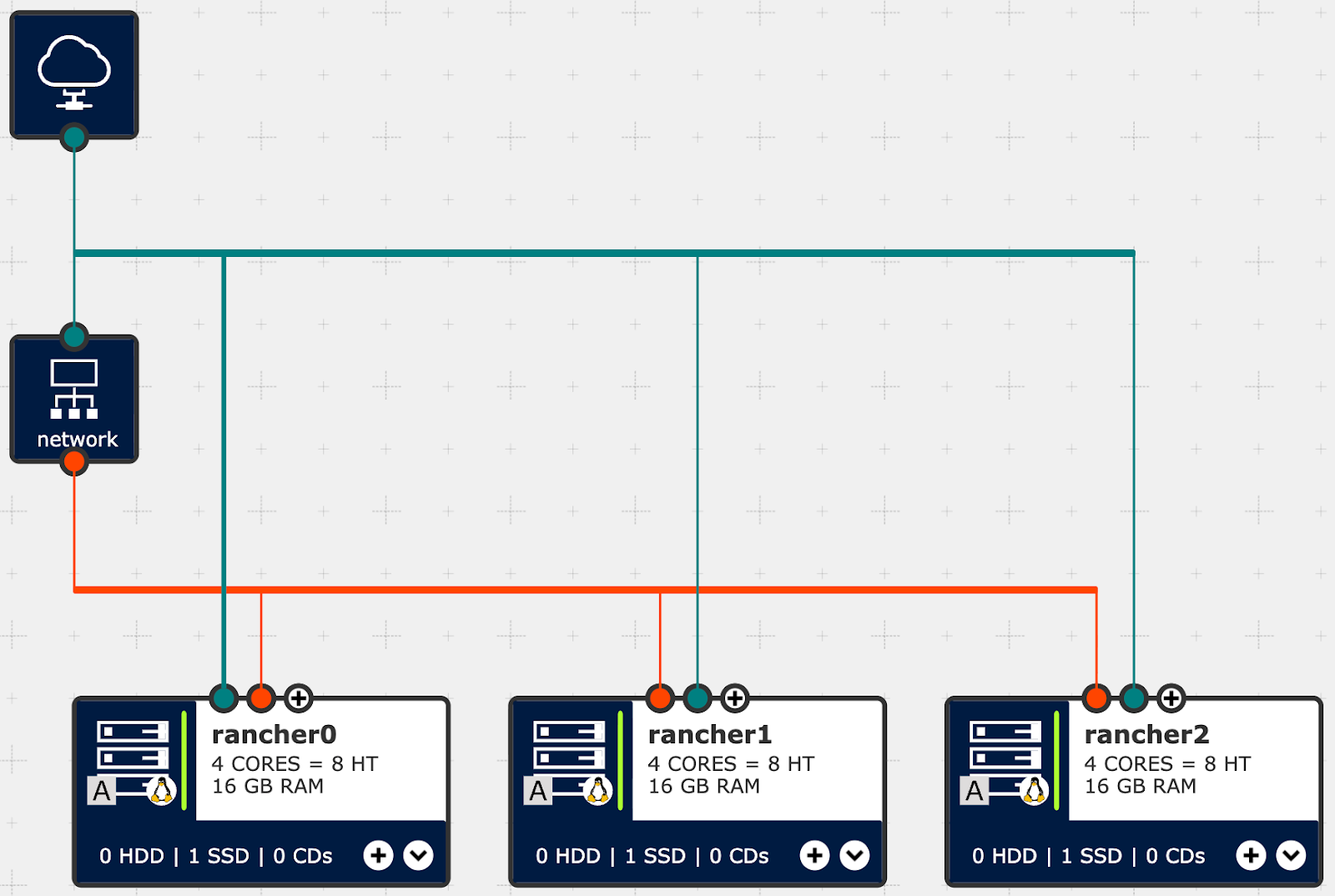
Figure 1: Rancher on IONOS Cloud, Architecture Diagram of infrastructure components
Distribute three control plane nodes across the infrastructure to form the Rancher Manager Cluster. An IONOS Network Load Balancer (NLB) is the entry point for traffic. The networking uses two separate LANs. A public LAN provides the nodes with direct internet access for updates and management. A private LAN handles internal communication between the nodes. Ingress traffic goes from the Load Balancer to the cluster via the private network.
We use Dedicated Core Servers and SSD Premium storage for the compute resources. This hardware matches the SUSE Rancher Prime on RKE2 requirements. It provides enough I/O and low latency for the etcd datastore.
Option 1: Manual Setup
Build the environment manually to see how components work together. The IONOS Data Center Designer (DCD) is the visual interface for this.
Open an existing Virtual Data Center, or create a new one. Figure 2 shows an example.
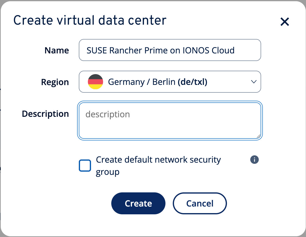
Figure 2: Create dialog for a new virtual data center called “SUSE Rancher Prime on IONOS Cloud” in the region “Germany / Berlin (de/txl)”
For the Rancher Manager Cluster, we use three virtual machines. Configure them with 4 dedicated cores and 16 GB RAM (Figure 3).
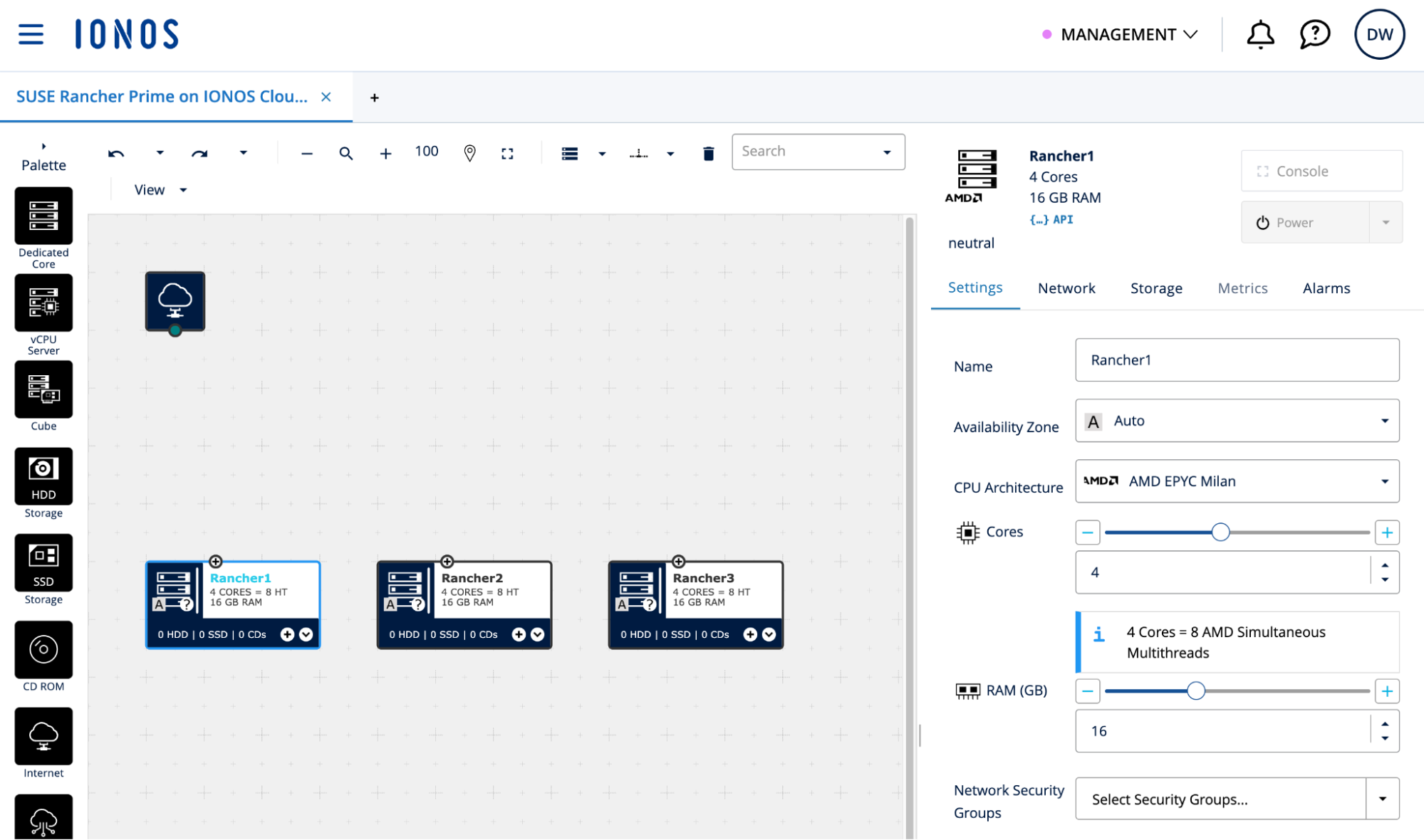
Figure 3: Three virtual machines in DCD with dedicated cores for the Rancher Manager Cluster
Create a 600 GB SSD Premium storage volume for each VM (Figure 4). Configure it using the SLES 15 SP7 BYOS image (Figure 5).
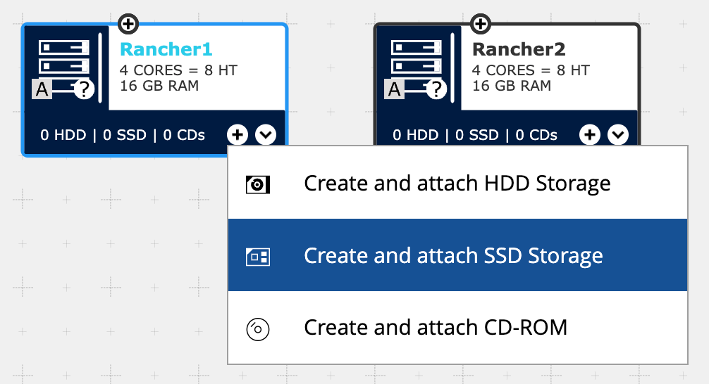
Figure 4: Create and attach a new SSD Storage volume to virtual machine Rancher1

Figure 5: The new storage volume is called “root”, has a size of “600 GB”, performance type “Premium” and uses the SLES15-SP7 BYOS image
IONOS scales I/O performance based on volume size. This provides the required IOPS for etcd. Figure 6 shows the three nodes with attached root volumes.
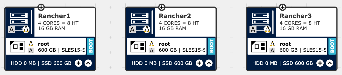
Figure 6: Virtual machines Rancher1, Rancher2 and Rancher3 with the newly created root volume
Each VM needs two network interfaces. One connects to the public LAN for internet connectivity (Figure 7). The second connects to the private LAN for internal cluster traffic (Figure 8). Further reading: Virtual Data Center networking.
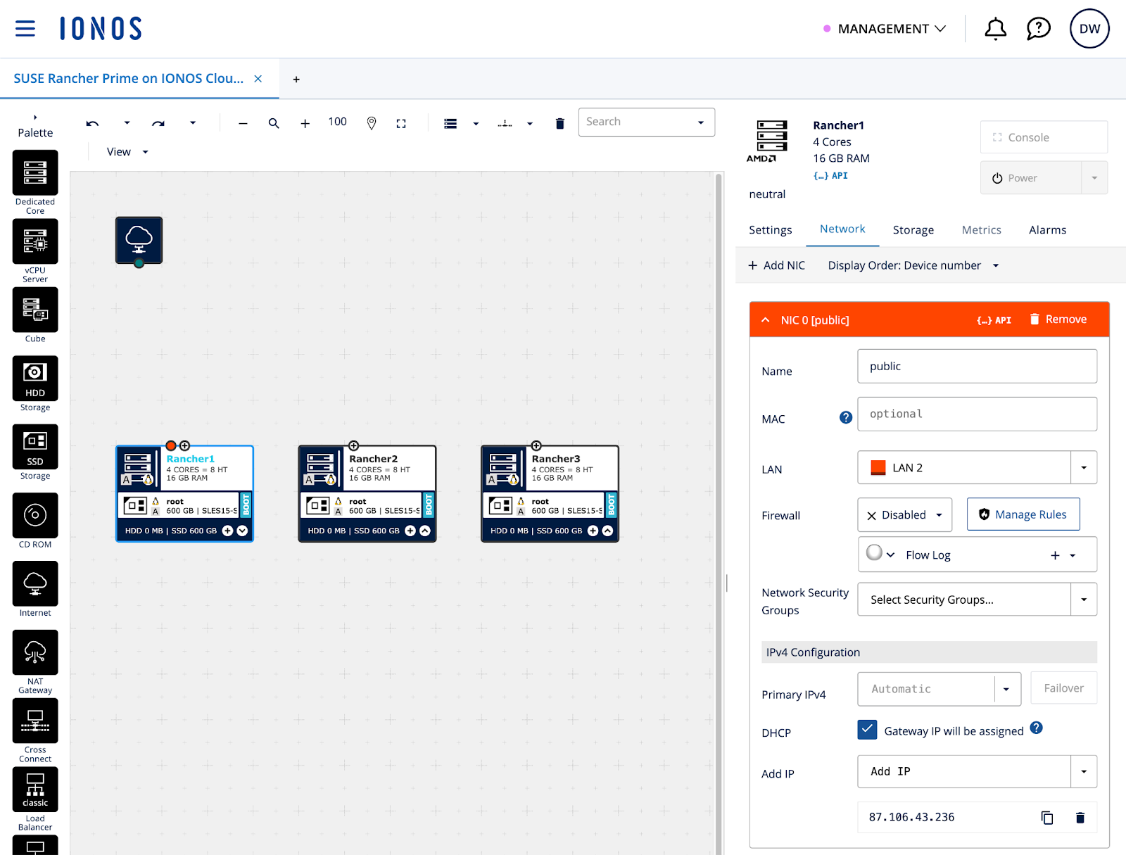
Figure 7: Public network interface on Rancher1 with a static public IP address
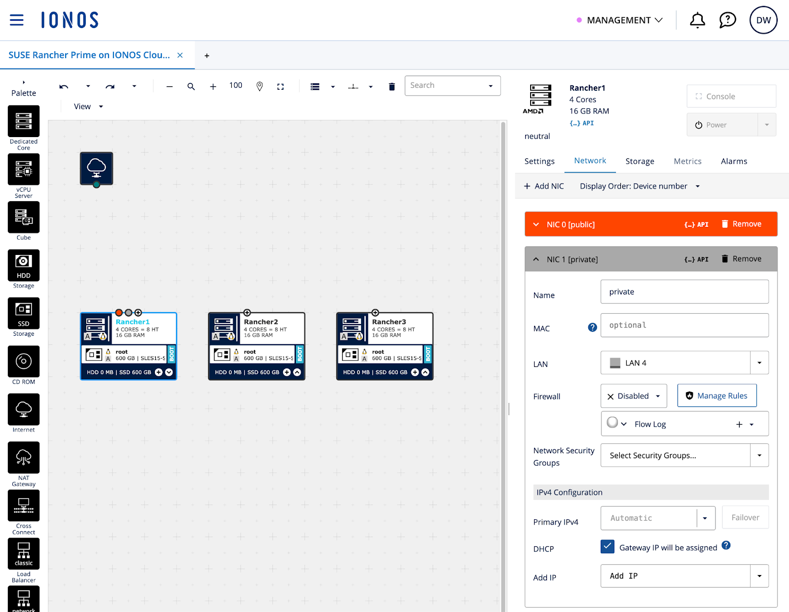
Figure 8: Private network interface on Rancher1 with a dynamic IP address
Repeat these steps on all three virtual machines. Connect them to the same LAN (NIC 0 = public, NIC 1 = private). See Figure 9 for the result.
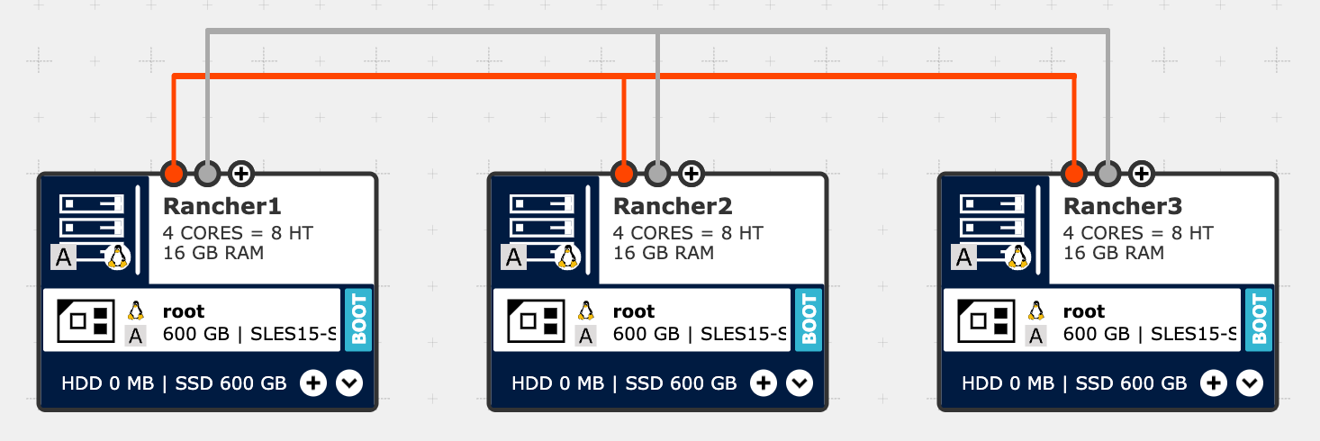
Figure 9: The three virtual machines Rancher1, Rancher2 and Rancher3 have a public and private network interfaces assigned to them and are connected to each other
The IONOS Network Load Balancer handles cluster ingress traffic. It runs TCP health checks to find responding targets. Then, it routes traffic to active nodes. Create a new instance in DCD, add a public and private IP address and connect the interfaces to the existing networks. See Figure 10 for the result.
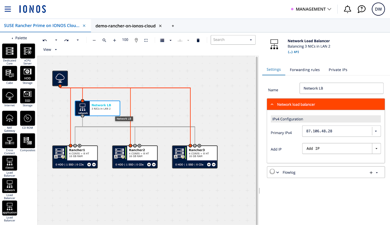
Figure 10: A new Network Load Balancer with a public and private IP address, connected to the existing LANs
Forwarding rules for TCP ports 80 and 443 handle Rancher UI traffic. Additional rules for TCP port 9345 allow new downstream nodes to register with the RKE2 cluster, and port 6443 serves the Kubernetes API. Further reading: RKE2: Configure the Fixed Registration Address
Figure 11 shows an example of such a Forwarding rule based on HTTP.
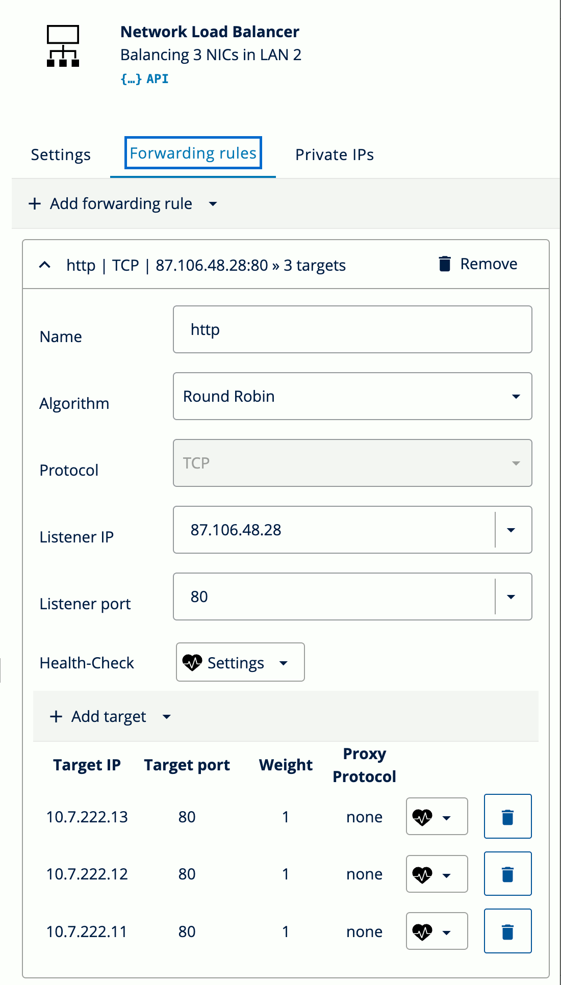
Figure 11: Network Load Balancer forwarding rule for HTTP traffic to the three Rancher Manager virtual machines
Add four rules for the different ports. Point all rules to the three virtual machines for the Rancher Manager (Figure 12).
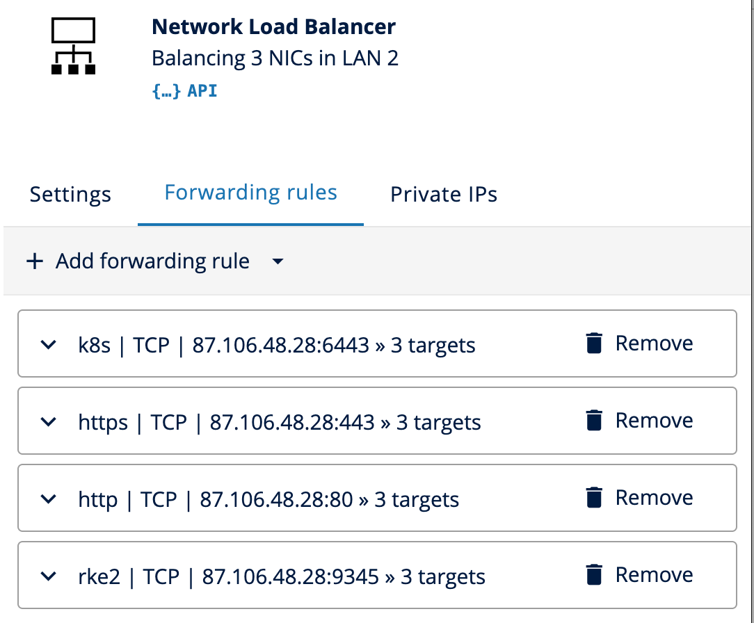
Figure 12: Network Load Balancer configuration completed with four forwarding rules to cover HTTP (80), HTTPS (443), RKE2 (9345) and K8s (6443)
Select “Provision Changes” in DCD and wait for the deployment to finish (Figure 13).
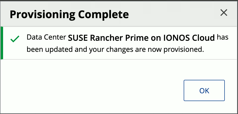
Figure 13: Confirmation that the Provisioning of the infrastructure in Data Center “SUSE Rancher Prime on IONOS Cloud” was completed successfully
Once the infrastructure is ready, SSH into the nodes to configure the software. The operating system has to be registered with the SUSE Customer Center using SUSEConnect.
Run these commands to register the virtual machine to SCC, install iptables, and apply updates:
SUSEConnect -r <REGISTRATIONCODE> -e <EMAIL>

zypper ref && zypper --non-interactive in iptables

zypper --non-interactive dup
Create the file “/etc/rancher/rke2/config.yaml” on all virtual machines as a privileged user. The “token” value must be identical on every node. Additional nodes use this to join the cluster. Set the “server” parameter only on the second and third nodes.
token: <SECRETCLUSTERTOKEN>

server: https://<LoadBalancerPublicIP>:9345

node-external-ip:  <VMPublicIP>
node-ip:           <VMPrivateIP>
advertise-address: <VMPrivateIP>

tls-san:
  - <LoadBalancerPublicIP>
  - <VMPublicIP>
Note: If DNS names are configured that point to the LoadBalancer and / or Virtual Machines, add them to the “tls-san” list as well. Further reading: RKE2: Installation – High Availability
Run the installation command on the first node to start the RKE2 cluster. You can adjust the version “v1.34.2+rke2r1” based on your needs and current requirements.
curl -sfL https://get.rke2.io --output install.sh

chmod +x install.sh

INSTALL_RKE2_VERSION="v1.34.2+rke2r1" ./install.sh
Important: If no custom “token” was set in the RKE2 config, then the node token must be retrieved from the initial server and configured on the additional nodes before running the RKE2 install script. This token is located at “/var/lib/rancher/rke2/server/node-token”.
Execute the join command, including the cluster token, on the remaining two nodes to complete the HA setup.
# Ensure parameters in “/etc/rancher/rke2/config.yaml” are set correctly
# Especially that "server" is configured before installation and cluster join

curl -sfL https://get.rke2.io --output install.sh

chmod +x install.sh

INSTALL_RKE2_VERSION="v1.34.2+rke2r1" ./install.sh
Refer to the official documentation for command syntax and execution details. Further reading: RKE2: Launch additional server nodes
The final step is installing Rancher Manager. Run this from a cluster server or a local machine. Prerequisites: kubectl, helm, and a valid kubeconfig.
Use the Helm CLI to deploy Cert-Manager, followed by the Rancher chart. SUSE Rancher Prime users should use the specific Prime chart repository. This grants access to the supported version. Community users can use the standard repositories.
Use Let’s Encrypt, self-signed certificates, or a private Certificate Authority (CA). Further reading: RKE2: Install/Upgrade Rancher on a Kubernetes Cluster
# SUSE Rancher Prime
# See: https://documentation.suse.com/cloudnative/rancher-manager/v2.12/en/installation-and-upgrade/install-rancher.html#_1_add_the_helm_chart_repository

helm repo add rancher-prime <AddHelmChartRepoURL>

# Rancher community
helm repo add rancher-stable https://releases.rancher.com/server-charts/stable

# Create namespace for Rancher
kubectl create namespace cattle-system

# Add the Jetstack Helm repository
helm repo add jetstack https://charts.jetstack.io

# Update local Helm chart repository cache
helm repo update

# Install the cert-manager Helm chart
helm install cert-manager jetstack/cert-manager \
  --namespace cert-manager \
  --create-namespace \
  --set crds.enabled=true

# Once cert-manager is installed, verify it is deployed correctly by checking the cert-manager namespace for running pods
kubectl get pods --namespace cert-manager

# Rancher Generated Certificates (Default)
helm install rancher rancher-<CHART_REPO>/rancher \
  --namespace cattle-system \
  --set hostname=<LoadBalancerPublicIPOrDNSName> \
  --set bootstrapPassword=<BootstrapPassword>

# Wait for Rancher to be rolled out
kubectl -n cattle-system rollout status deploy/rancher
Rancher Manager is now up and running and accessible via HTTPS through the Network Load Balancer public IP address or DNS Name.
Enter the custom Bootstrap password or retrieve it via the kubectl command in Figure 14.
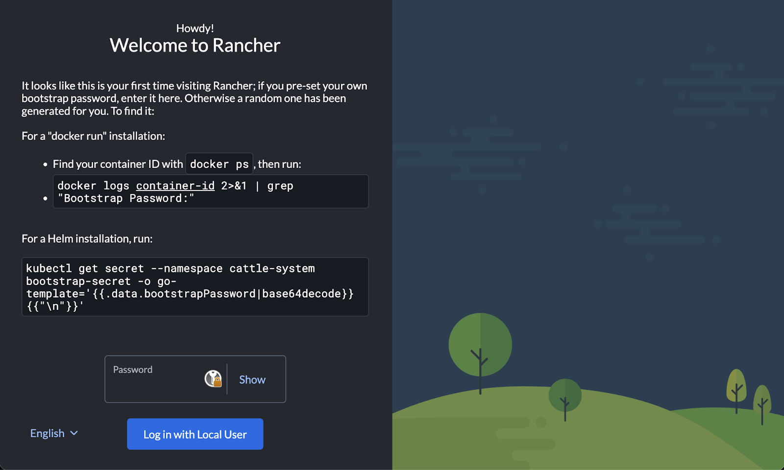
Figure 14: Rancher Manager initial setup screen with instructions to retrieve and provide the Bootstrap password
Set a password for the admin user and confirm or adjust the Rancher Manager Server URL and accept the EULA (Figure 15).
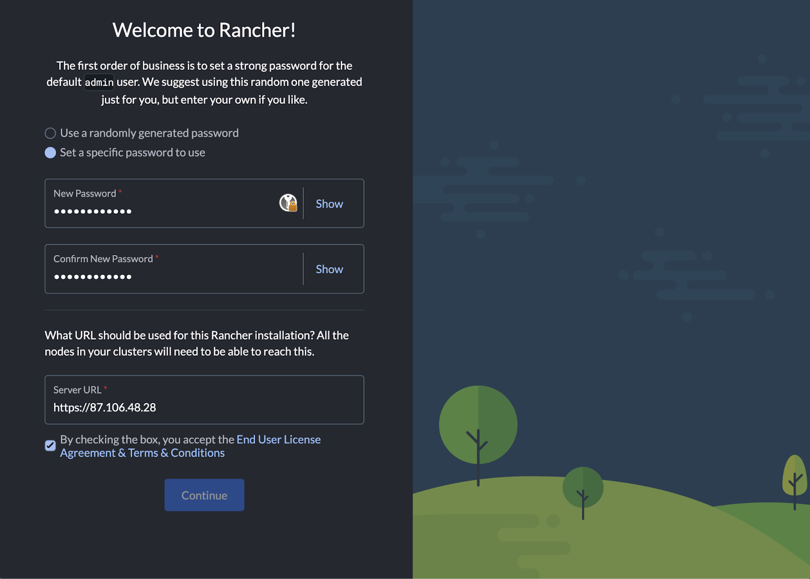
Figure 15: Rancher Manager welcome screen to provide a new password for the admin user and to confirm or adjust the Server URL
After completion, the Welcome to Rancher screen and Cluster Overview shows up (Figure 16).
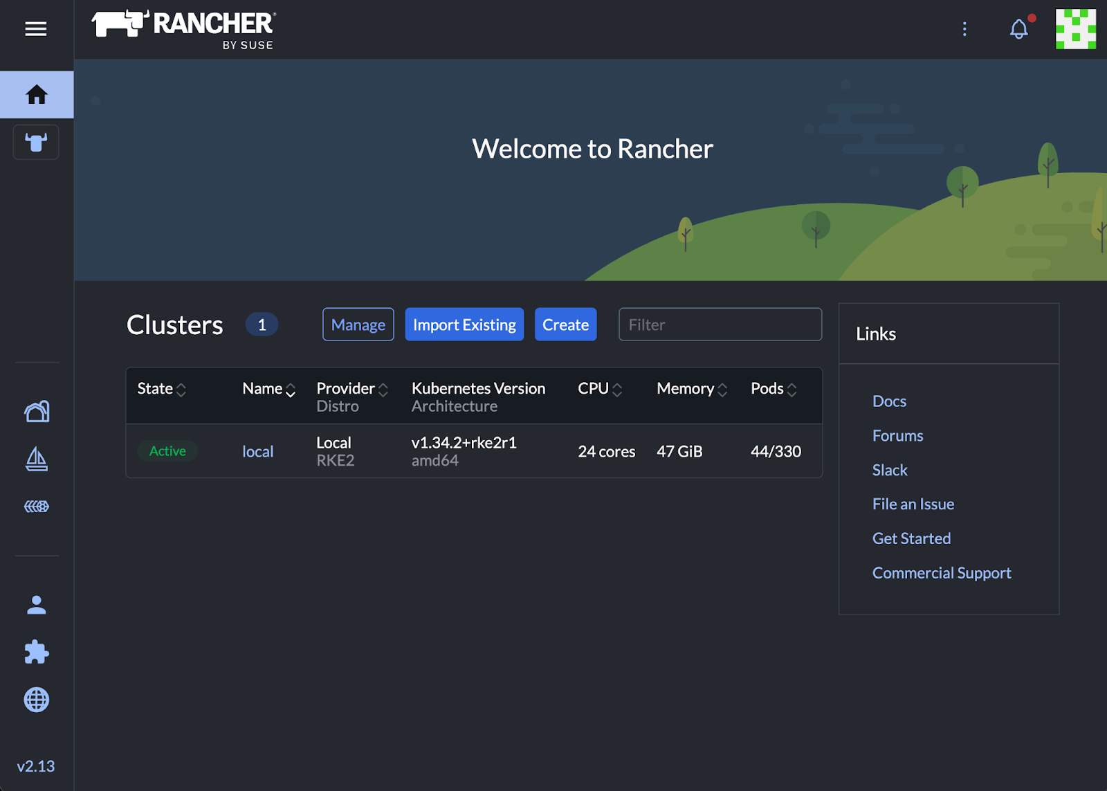
Figure 16: Welcome to Rancher screen and Clusters Overview after successful completion of the initial setup
Option 2: Automated Setup
To automate the infrastructure, use our Demo: Rancher on IONOS Cloud repository.
This code automates the setup. It defines the Virtual Data Center and LANs. Deploys network load balancer and virtual machines. Also configures the dual-network interfaces and storage settings.
The configuration is modular. It uses the official ionos-cloud provider and the tf-rancher-up modules. The RKE2 module uses cloud-init to automate the software bootstrapping. It registers IONOS servers with SCC, downloads RKE2, and joins the cluster on boot. The Rancher module handles the Helm chart installation. It waits for the Kubernetes API to become healthy and then deploys Cert-Manager and Rancher.
Use this code as a reference and blueprint for your own Infrastructure as Code (IaC) automation. Deployment variables are customized in a terraform.tfvars file. Running terraform apply or tofu apply spins up the infrastructure components, configures the load balancer forwarding rules, and starts the software installation. The output provides the URL of the Rancher Manager once the process completes.
The project README provides all the details how to configure and use it.
Conclusion
You have deployed a Highly Available Rancher Manager on IONOS Cloud. This blog showed the manual setup to explain the architecture. It also covered the automated Infrastructure as Code approach.
This environment gives you a robust foundation for Kubernetes management. It combines open source flexibility with a European provider to support your data sovereignty goals. You now have a platform that prioritizes local data control.
The Management Cluster is running. Now, onboard workloads by registering existing Kubernetes clusters or launching new ones on existing custom nodes.
We will publish more information on using the IONOS Cluster API (CAPI) provider soon. We also plan technical sessions about Rancher on IONOS Cloud.
Related Articles
Apr 26th, 2024
What’s New in SUSE ATIP 3.0?
Apr 03rd, 2025